TRENDnet TV-IP400 User Manual
Hide thumbs
Also See for TV-IP400:
- User manual (106 pages) ,
- Frequently asked questions manual (14 pages) ,
- Quick installation manual (13 pages)
Table of Contents
Advertisement
Quick Links
Advertisement
Table of Contents

Related Manuals for TRENDnet TV-IP400


Summary of Contents for TRENDnet TV-IP400
-
Page 2: Table Of Contents
ABLE OF ONTENTS ABOUT THIS GUIDE ...........3 INTRODUCTION ............4 ..........5 EATURES AND ENEFITS ..........7 NPACKING THE ACKAGE .............8 YSTEM EQUIREMENT ............9 HYSICAL ESCRIPTION HARDWARE INSTALLATION ........12 ........12 TTACHING THE ETAL LATE .......13 ONNECTING THE THERNET CABLE ........13 TTACHING THE OWER UPPLY SECURITY ..............14 APPLICATION ..............15... - Page 3 ..........68 ONFIGURING THE YSTEM APPENDIX ..............82 A. F .......82 REQUENTLY SKED UESTIONS B. PING Y IP A ..........85 DDRESS C. T ...........86 ROUBLE HOOTING D. T ............90 ABLE E. X .........92 PLUG ONTROL NSTALLATION F. A ......95 DJUST NTERNET AMERA OCUS G.
-
Page 4: About This Guide
BOUT UIDE This manual provides instructions and illustrations on how to use your TV-IP400/TV-IP400W Pan/Tilt (Wireless) Internet Camera, includes: Chapter 1, Introduction, provides the general information on the camera. Chapter 2, Hardware Installation, describes the hardware installation procedure for the camera. -
Page 5: Introduction
NTRODUCTION Thank you for purchasing the TV-IP400/TV-IP400W Pan/Tilt (Wireless) Internet Camera, a standalone system that can be connected directly to an Ethernet or Fast Ethernet. TV-IP400W also supports in addition wireless transmission that based on the IEEE 802.11g standard. Compared to the conventional PC... -
Page 6: Features And Benefits
Features and Benefits Simple to Use The TV-IP400/TV-IP400W Pan/Tilt Internet (Wireless) Camera is a standalone system with built-in CPU, no special hardware (such as a PC frame capture card) or software required. The camera supports DirectX 9.0; therefore, the only requirement you need is the web browser software such as Internet Explorer 5.0 or... - Page 7 Remote Utility The powerful IPView Pro application assigns the administrator with a pre-defined user ID and password, allowing the administrator to modify the camera settings from the remote site via Intranet or Internet. When new firmware is available, you can also upgrade remotely over the network for added convenience.
-
Page 8: Unpacking The Package
Unpacking the Package Unpack the package and check all the items carefully. One TV-IP400/TV-IP400W One Detachable Antenna (TV-IP400W only) One Multi-Language Quick Installation Guide One Driver & Utility CD-ROM with User’s Guide One External Power Adapter (5V DC, 2.5A) One RJ-45 Ethernet Cable... -
Page 9: System Requirement
System Requirement Networking Local Area Network: 10Base-T Ethernet or 100Base-TX Fast Ethernet Wireless Local Area Network (TV-IP400W only): IEEE 802.11g Wireless LAN Accessing the Camera For Web Browser Users Operating System: Microsoft® Windows® 98SE/ME/ 2000/XP CPU: 300 MHz or above Memory Size: 32MB (64MB recommended) Resolution: 800x600 or above Microsoft®... -
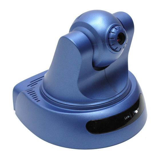
Page 10: Physical Description
Physical Description This section provides the information of camera and explains the function of each component. Front Pane, Top/Bottom Panel There are two LED indicators on the front panel of the camera: Power LED and Link LED. 1. Detachable Antenna The detachable external antenna allows you to adjust its position to obtain the maximum signal. -
Page 11: Link Led
2. Link LED The Link LED is positioned on the left side of the two LEDs. A steady ORANGE light confirms that the camera has good connection to LAN connectivity. Dependent on the data traffic, the LED will begin to flash to indicate that the camera is receiving/sending data from/to the network. -
Page 12: Power Connector
1. Power Connector The DC power input connector is located on the camera’s rear panel, and is labeled DC5V 2.5A with a single jack socket to supply power to the camera. Power will be generated when the power supply is connected to a wall outlet. 2. -
Page 13: Hardware Installation
ARDWARE NSTALLATION Attaching the Metal Plate Wall screw Screw Ceiling screw Screw Wall screw Ceiling screw Base of the camera To attach the metal clip, remove the two rubber pads under the base of the camera firstly. Place the metal clip onto the camera base, and align the two holes of metal clip with two screw holes on the base. -
Page 14: Connecting The Ethernet Cable
Connecting the Ethernet cable Connect an Ethernet cable to the network cable connector located on the camera’s rear panel, and then attach it to the network Attaching the Power Supply Attach the external power supply to the DC power input connector located on camera’s rear panel, and then connect it to your local power supply. -
Page 15: Security
ECURITY To ensure the highest security and prevent unauthorized usage of the camera the Administrator has the exclusive privilege to access the System Administration for settings and control requirements to allow users the level of entry and authorize the privileges for all users. -
Page 16: Application
PPLICATION The TV-IP400/TV-IP400W camera can be applied in wide variety of applications. Including: Monitoring of local and remote places and objects such as construction sites, hospitals, amusement parks, schools and day-care centers through the use of a web browser. Capture single frame images from the IPView Pro application. -
Page 17: Application Diagrams Of The Camera
Application Diagrams of the Camera Home or business Applications... -
Page 18: Using The Camera
SING THE AMERA You can access and manage the camera through: 1) a web browser, and 2) the enclosed software IPView Pro. This chapter describes the Web Configuration Utility, and provides the instructions on using the camera with a web browser. Web Configuration Utility The camera must be configured through its built-in Web-based Configuration. - Page 19 Default IP address Pre-view area Welcome Screen of the Configuration Utility After the default IP address is entered from the browser, the camera Welcome screen will appear with a still image. There will be three options to choose from to set-up and view your camera, including: Home –...
-
Page 20: Administration
Administration On the Welcome screen of the Configuration Utility, click Administration to enter the administration window that contains the settings required for the camera in the top menu bar, including Status, Configuration, Tools and Help TIP: Click Save to store the setting, or Cancel to abandon, or Refresh to reload the status. - Page 21 System Click the System item in the left column to display the device status of your camera (as shown above). - Device Status: The information about the camera, including the Camera Name, Location, Model, Firmware Version, MAC Address and IP Address, can be found in this field.
- Page 22 - Ethernet Status: You can monitor the networking status in this field, including the Link (network connection), Speed, and the Duplex mode. Video Click the Video item in the left column to display the video configuration of your camera.
- Page 23 - Video Status: The video configuration about the camera, including the Video Resolution, Compression Rate, Frame Rate, Frame Size and IP Address, can be found in this field. Wireless( for TV-IP400W only) Click the Wireless item in the left column to display the information of the wireless LAN.
-
Page 24: Active Users
- Network Status: The items in this field display the information of the LAN, such as the IP Address, Subnet Mask, Default Gateway, Primary/Secondary DNS Address, Dynamic DNS, Secondary HTTP Port, UPnP, as well as the FTP/E-mail upload status. Active Users Click the Active Users item in the left column to display the user(s) information. - Page 25 - Active Users: The items in this field display the user(s) information, including the user(s) IP address, Name, and DateTime.
- Page 26 Administration Configuration The Configuration window contains commands for settings that are required to input key details to setup the camera for operation. Click Configuration in the top menu bar and the Configuration window will appear as below: System Click the System item in the left column to setup the basic configuration of your camera.
- Page 27 - System Setting: In this field, you can configure the basic information of your camera. Camera Name: This field is used to enter a descriptive name for the device. The default setting for the Camera Name is CS-xxxxxx, where xxxxxx the last six digit of the MAC Address.
- Page 28 The default setting for administrator is blank space (Null String), and you need to key in the administrator name with a maximum length of 12 (printable ASCII) characters enter administrator password with a maximum length of 8 (printable ASCII) characters. It is highly recommended to set the Admin ID and Admin Password as soon as possible to enable security option for the camera to function.
- Page 29 - Video Setting: In this field, you can configure the basic information of your camera. Video Resolution: Select desired video 160x120 320x240 resolution format, including 640x48 (default) and desired Compression Rate: Select compression rate with five levels from Very Low to Very High.
- Page 30 Brightness Control: Adjust the brightness level with default setting at 64. Contrast Control: Adjust the contrast level with default setting at 64. Saturation Control: Adjust the saturation with default setting at 64. Light Frequency: Adjust the light frequency to suit your area of operation from the options either 50 Hz or 60 Hz (default).
- Page 32 - Wireless Interface Connection Mode: Use this option to determine the type of wireless communication for your camera. There are two choices of Infrastructure mode and Ad- Hoc mode. The default setting is Infrastructure. SSID: The SSID (Service Set Identifier) is the name assigned to the wireless network.
- Page 33 Wireless Channel: This pull-down menu provides the wireless channel for communication. "channel" is a range of frequencies to be used in communication between the camera and access point Infrastructure mode, camera PC/Notebook in Ad-Hoc mode. Select the appropriate channel from the list provided depending on the regulatory region where the unit is sold.
- Page 34 intercepted communications extremely difficult to The default interpret by unauthorized parties. setting for this option is Disable. WEP Key Length: Select the proper setting for WEP Encryption. In general, a larger key length creates a stronger cipher. The default is 64-bits. WEP Key Format: To enable WEP Encryption, you should decide the encryption format first by selecting the ASCII or HEX option, and then input the WEP...
- Page 35 Encrypt Data Transmissions Using: Use this pull- down menu to decide to use Key 1, 2, 3 or 4 for encryption). WPA-PSK: This is a special mode designed for home and small business users who do not have access to network authentication servers. In this mode, the user has to manually enter the starting password in their access point or gateway, as well as...
- Page 36 Network Click the Network item in the left column to setup the LAN configuration of your camera. - TCP/IP: The items in this field display the information of the local area network. IP Address Mode: This field provides your with three options to select the IP Address Mode: You can select this option and enter the IP Fixed IP...
- Page 37 Subnet Mask – 255.255.255.0 Default Gateway – 0.0.0.0 If your network uses the DHCP server, select this option. According to this setting, Dynamic the camera will be assigned an IP address Address from the DHCP server automatically. Every (DHCP) time when the camera starts up, please make sure that the DHCP server is set to assign a static IP address to your camera.
- Page 38 User Click the User item in the left column to add, edit and delete users for your camera. - User Access Control: Access Control: The administrator has the authority to give permission for the privilege to control the device to users by selecting Enable or Disable. The default setting is No.
- Page 39 Add User: Enter the user name in this box, and enter the user’s password assigned by the administrator. The maximum password length is 8 (printable ASCII). The administrator has the authority to give permission for the privilege to control the Upload/E- mail Video control to the users by selecting Yes or No to activate the Upload/E-mail Video.
- Page 40 - Date & Time: You can set up time and date manually or automatically by selecting the Synchronized with Time Server option. Synchronized with Time Server: Select this option and the time will be based on GMT setting. The time will be synchronized every 10 minutes.
- Page 41 Set Manually: Select this option to set the time manually. The system administrator must enter the date and time in the respective field manually. Upload Click the Upload item in the left column to setup configuration for FTP server, time schedule and manual operation.
- Page 42 - FTP Server: This field contains the following six basic settings for your FTP server. Host Address: The IP Address of the target FTP server.
- Page 43 Port Number: The standard port number for the FTP server is Port 21, and it’s also the default setting. If the FTP server uses a specific port, please confirm the IT manager. User Name: Enter the user name in this field. Password: Enter the user password in this field to login the FTP server.
- Page 44 - Manual Operation: When you click the Upload Video button in view video screen, it will start to upload the image. The setting refers to Base File Name and File information above. E-mail Click the E-mail item in the left column to setup configuration for E-mail account, time schedule and manual operation settings.
-
Page 45: Administration Tools
SMTP Server Address: SMTP (Simple Mail Transfer Protocol) is a protocol for sending e-mail messages between servers you need to input the mail server address in this field. Sender e-mail Address: Enter the e-mail address of the user who will send the e-mail. Receiver e-mail Address: Enter the e-mail address of the user who will receive the e-mail. -
Page 46: Ftp Server Test
FTP Server Test Click the FTP Server Test item in the left column to test your FTP server (as shown above). - Test FTP Server: Click the Test button to test the FTP server you provided. E-mail Test Click the E-mail Test item in the left column to test your e-mail account. - Page 47 - Test E-mail Account: Click the Test button to test the e- mail account you provided. Reset Do you really want to reset this device? Click the Yes button from this option, and you can restart the camera just like turning the device off and on and saved settings are retained.
-
Page 48: Factory Reset
Factory Reset Do you really want to factory reset this device? Click the Yes button from this option, and you can resume all factory default settings for the camera. If you do not want to restore the factory settings, exit this window without clicking Yes. Please NOTE that you have to configure the network settings again after a Factory Reset. -
Page 49: Firmware Upgrade
Firmware Upgrade When new firmware is available, you can upgrade it through this window. Click the Browse… button to point to the firmware file, and then click Update to start upgrading. - Page 50 Backup Click the Backup item in the left column to backup the current configuration. - Backup Device Configuration to File: Do you really want to backup the configuration to file? Click the Backup button from this option, and you can save the current configuration to file.
- Page 51 Administration Help The Help window provides the basic information of the camera. Click Help in the top menu bar and the Help window will appear as below: About Displays the camera’s model name and version. Once the configuration is completed, click Home to return to the Welcome screen and select the desired View Video option either through ActiveX Mode or Java Mode as described in the next section.
-
Page 52: Viewing Video
desire image quality. Please refer to Appendix F for detailed instruction. Viewing Video To view video images from the browser, click View Video – ActiveX Mode or Java Mode from the Welcome screen to access the video images from your browser. Camera Name and Date/Time Camera Name and... - Page 53 Camera Name & Date/time: The Camera name and the current date/time will be displayed when the related information are entered under Configuration of Web Configuration Utility. Uploading/E-mailing Video In the View Video – ActiveX Mode or Java Mode, you are allowed to use the Upload Image and E-mail Image options.
-
Page 54: Controlling The Camera
Controlling the Camera You can control the camera’s viewing angle through the control buttons on the left side of the viewing window. Control buttons Adjusting the Viewing Angle To adjust the camera’s viewing angle, simply click the Up/Down/ Left/Right button. Then, you can easily move the camera’s lens to focus on the object that you want. - Page 55 Storing the Position You can store the position(s) that you want to monitor, so that you can quickly move the camera’s lens to focus on the object that you want. You can store up to 24 positions in the camera (the number “0”...
-
Page 56: Ipview Pro
This chapter describes the IPView Pro, which is a powerful software application designed with a user-friendly interface for ease of control and navigation requirements. Installation Step 1 Insert the CD-ROM into the CD-ROM drive to initiate the auto- run program. Once completed, a menu screen will appear as below:... - Page 57 Step 2 Click the IPView item to activate the InstallShield Wizard. Click Next in the welcome screen. Step 3 Read and accept the License Agreement; then, click Yes.
- Page 58 Step 4 Choose the destination location. If no specific requirement, leave the default setting and click Next. Step 5 The InstallShield Wizard starts to install the software, and the progress bar indicates the installation is proceeding.
- Page 59 Step 6 Click Finish to complete the installation.
-
Page 60: Getting Started
Getting Started This section describes the User Interface of IPView Pro, with detailed procedures for using the application. To launch IPView Pro, click Start > Programs > IPView Pro > IPView Pro. The main screen will appear as below: NOTE: IPView Pro requires the system’s resolution setting up to 1024x768. Please configure the resolution to 1024x768 or higher;... -
Page 61: Item Feature
Item Feature Item Description Date/Time Show current date/time. Status Mode Show the camera’s status in this window. Window Click the Change Status Mode button ( ) on the right lower corner of the window to change the display mode: Camera list mode Camera information mode View Window Show the camera’s view in this window. - Page 62 12 Control Button Click the Right/Left or Up/Down button to control your camera viewing angel. (For TV-IP400 & TV-IP400W models only) 13 Record Button Record video clip of the selected camera and save it in the computer. The storage position can be configured in System Configuration.
-
Page 63: Using Ipview Pro
Using IPView Pro Adding a Camera To add a camera: 1. Click the System Configuration button to enter the System Configuration. If you are not sure of the camera’s IP address, you can click Search to search the available camera(s) within the network. - Page 64 2. Select the camera you want by highlighting it, and then click Add Camera. The camera is added. Click the Add Camera button. The camera found within the network. 3. Click Save, and then click the System Configuration button to return to View Window.
- Page 65 Alternately, you can add a camera by entering the its IP address directly: 4. Select the Input IP tab. The camera is added. Click the Add Camera button. Enter the camera’s IP address and Port. 5. Enter the camera’s IP address (default: 192.168.1.30) and Port (default: 80), and then click Add Camera.
-
Page 66: Removing A Camera
Removing a Camera To remove the camera from the list: camera elect the you want to remove. 2. Click Delete Camera. -
Page 67: Viewing A Camera
Viewing a Camera From the View Modes of the panel, you can select one-camera mode or other modes to display your video. IPView Pro allows a maximum of 16 cameras for viewing. For example, if you use only one camera, select one-camera mode ( ), and the View Window will display the view as figure 1. -
Page 68: Recording Video
Recording Video IPView Pro allows you to record the video clip and save it in your computer through the following methods: Manual Record, Schedule Record, and Motion Record. When you click the Record button and select Manual Record, it will start recording. Click the button again to stop. If you select Schedule Record or Motion Record, the system will record the video clip according to the settings in System Configuration. -
Page 69: Configuring The System
Select the recorded file in the computer, and then click OK. Configuring the System Clicking the System Configuration button on the panel allows you to configure the system settings, and the System Configuration Screen will appear in the View Window as shown below. Once configured, click Save to save the settings, and then click the System Configuration button again to exit configuration. -
Page 70: Camera Configuration
Camera Configuration In this field, you can add/delete the camera (as described in the previous section). Also, you can configure the following settings: Web Configuration In the top low, selecting the Administration item will launch the Web Configuration Utility in View Window. You can configure these settings according to the description in Chapter 5, Using the Camera. - Page 71 Motion Configuration-1 The Motion Configuration-1 item provides the commands for motion detection control. Before configuring, you should select one camera from the pull-down menu. Select one camera. Select Custom region. Region 1. Region 2. Detect Region: Full picture – When you select this option, the camera will monitor the whole area.
- Page 72 recording automatically. You can set multiple areas in the view screen. Click Delete Region to remove the area selected. Click Clear All Region to remove all areas in the view screen. Sensitivity Level: Move the slide bar to adjust the sensitivity level for detecting motion to record video.
- Page 73 Invoke Alarm: Select this option to enable alarm when some motion detected by the system. Send e-mail: When this option is checked, click the Mailing Configuration in the left column to enter the required information (see the following section). Play music: You can use the music file to alert the event. Click Browse music file to select the desired music, and set the Interval time.
-
Page 74: Mailing Configuration
Reset: Restore the original setting of your camera. Do you really want to reset this device? Click Yes in the pop-up dialog box to confirm. Factory Reset: Restore the factory default settings of the camera. Do you really want to factory reset this device? Click Yes in the pop-up dialog box to confirm. -
Page 75: Proxy Server
Mail Server: Enter the mail server address that is used to send your e-mail. Mail From/To: Enter the sender’s/receiver’s e-mail address. Subject: Enter the title of the e-mail. User Name/Password: Enter the user name/password to login the mail server. Interval Time: Enter a number in this box to setup the time (in second) to send e-mail regularly. -
Page 76: Recording Configuration
Recording Configuration In this field, you can configure the storage settings. Log Storage: Reserved HDD Space For MS-Windows OS – You can reserve 500 MB to 10000 MB hard disk space for the program. Each Recording File Size – If the recorded video files reach the file size limit, video images will be recorded into another file automatically. - Page 77 destination folder; click Delete to remove a selected path setting. Please note that you are not allowed to delete a path setting if there is only one setting in the list. Recycle: You can check this option to clear the files when the unreserved space of your hard disk is filled.
- Page 78 Date Mode: First, select the camera desired from the pull- down menu. Then, setup the time in the Start/Stop fields. Click Add to add the recording schedule to the list. Click Save to save the settings. Weekday buttons. Week Mode: First, select the camera desired from the pull- down menu.
-
Page 79: Log List
your time settings. The range of Time interval of scan is from 1 to 20 seconds. Log List This filed displays the user(s) information, which includes the Date, MAC address, and the brief description of events. - Page 80 Account This filed allows you to set the Admin ID and Admin Password. You can also check the Login password check option to secure your camera by checking the login password.
- Page 81 About This filed provides information of the software application.
-
Page 83: Appendix
PPENDIX A. Frequently Asked Questions Internet Camera Features Q: What is an Internet Camera? A: The camera is a standalone system connecting directly to an Ethernet or Fast Ethernet network and supported by the wireless transmission based on the IEEE 802.11g standard. It is different from the conventional PC camera, the camera is an all-in-one system with built-in CPU and web-based solutions providing a low cost solution that can transmit high... - Page 84 Q: What algorithm is used to compress the digital image? A: The camera utilizes the JPEG image compression technology providing high quality images for users. JPEG is adopted since it is a standard for image compression and can be applied to various web browser and application software without the need to install extra software.
- Page 85 Q: What network cabling is required for the camera? A: The camera uses Category 5 UTP cable allowing 10 Base- T and 100 Base-T networking. Q: Can the camera be setup as a PC-cam on the computer? No, the camera is an Internet Camera used only on Ethernet and Fast Ethernet network and supported by wireless transmission.
-
Page 86: Ping Your Ip A
B. PING Your IP Address The PING (Packet Internet Groper) command can determine whether a specific IP address is accessible by sending a packet to the specific address and waiting for a reply. It can also provide a very useful tool to confirm if the IP address conflicts with the camera over the network. -
Page 87: Trouble Shooting
C. Trouble Shooting Q: I cannot access the camera from a web browser. A1: The possible cause might be the IP Address for the camera is already being used by another device. To correct the possible problem, you need to first disconnect the camera from the network. - Page 88 A3: Other possible problems might be due to the network cable. Try replacing your network cable. Test the network interface of the product by connecting a local computer to the unit, utilizing a standard Crossover (hub to hub) Cable. If the problem is not solved the camera might be faulty.
- Page 89 A2: The default router setting might be a possible reason. Need to double check if the configuration of the default router settings is required. Q: Why does a series of broad vertical white line appears through out the image? A: A likely issue is that the CMOS sensor becomes overloaded when the light source is too bright such as direct exposure to sunlight or halogen light.
- Page 90 Q: There is poor image quality, how can I improve the image? A1: A probable cause might be the incorrect display properties configuration for your desktop. You need to open the Display Properties on your desktop and configure your display to show at least 65’000 colors for example at least 16- bit.
-
Page 91: Time Zone Table
D. Time Zone Table... -
Page 93: Xplug Controli
E. Xplug Control Installation Installation To Local PC Insert the CD-ROM into the CD-ROM drive to initiate the auto- run program. Once completed, a menu screen will appear as below: To install Xplug Control, click the Xplug Control item to activate the installation procedure for the plug-in program. - Page 94 Once executed, a prompt will appear requesting the input of the desired language selection. Make the desired selection and click OK to continue. Click the Next button to The Welcome screen will appear. proceed with the installation.
- Page 95 The License Agreement prompt will appear as below. Read the details carefully and click the Yes button to continue with the installation procedure. Click the Finish button to complete Setup of the Xplug Control Utility program for the camera.
-
Page 96: Adjust Internetc
F. Adjust Internet Camera Focus To adjust the focus of the lens, you need to turn the lens slowly in either clockwise or anti-clockwise direction until the desired image appears. DO NOT over turn the lens in either of the directions, as it will be out of focus. -
Page 97: Specification
G. Specification Image Sensor Sensor resolution : 640 x 480 pixel Sensor type : ¼” Color CMOS Sensor Lens : f: 6.0 mm, F: 1.8 Video Image compression : JPEG Image Frame rate : 30fps @ QQVGA, 25fps @ QVGA, 10fps @ VGA Compression Rate selection : 5 levels: Very low/Low/... - Page 98 : RDC R2880 : 8MB Flash ROM : 2MB : RTOS Power Supply : DC 5V 2.5A, switching type Power consumption : 8Watt (1600mA x 5V) LED Indicator : Power LED (Blue) Link LED (Orange) Pan/Tilt : Pan -156°~ +156° Tilt -45 ~ +70°...
-
Page 99: Glossary Of Terms
H. Glossary of Terms NUMBERS 10BASE-T 10BASE-T is Ethernet over UTP Category III,IV, or V unshielded twisted-pair media. two-pair twisted-media implementation 100BASE-TX 100BASE-T is called 100BASE-TX. An IEEE standard for wireless local area networks. It 802.11g offers transmissions speeds at up to 54 Mbps in the 2.4- GHz band. - Page 100 Address Resolution Protocol. ARP is a protocol that resides at the TCP/IP Internet layer that delivers data on the same network by translating an IP address to a physical address. Audio Video Interleave, it is a Windows platform audio and video file type, a common format for small movies and videos.
- Page 101 addresses to devices on a network. With dynamic addressing, a device can have a different IP address every time it connects to the network. In some systems, the device's IP address can even change while it is still connected. DHCP also supports a mix of static and dynamic IP addresses.
- Page 102 Ethernet The most popular LAN communication technology. There are a variety of types of Ethernet, including 10 Mbps (traditional Ethernet), 100 Mbps (Fast Ethernet), and 1,000 Mbps (Gigabit Ethernet). Most Ethernet networks use Category 5 cabling to carry information, in the form of electrical signals, between devices. Ethernet is an implementation of CSMA/CD that operates in a bus or star topology.
- Page 103 Short for hexadecimal refers to the base-16 number system, which consists of 16 unique symbols: the numbers 0 to 9 and the letters A to F. For example, the decimal number 15 is represented as F in the hexadecimal numbering system. The hexadecimal system is useful because it can represent every byte (8 bits) as two consecutive hexadecimal digits.
- Page 104 format used to route the information. Your Internet service provider controls the IP address of any device it connects to the Internet. The IP addresses in your network must conform to IP addressing rules. smaller LANs, most people will allow the DHCP function of a router or gateway to assign the IP addresses on internal networks.
- Page 105 Local Area Network a computer network that spans a relatively small area sharing common resources. Most LANs are confined to a single building or group of buildings. Network Address Translator generally applied by a router, that makes many different IP addresses on an internal network appear to the Internet as a single address.
- Page 106 NWay Protocol A network protocol that can automatically negotiate the highest possible transmission speed between two devices. PING Packet Internet Groper, a utility used to determine whether a specific IP address is accessible. It functions by sending a packet to the specified address and waits for a reply.
- Page 107 for transferors the medium include token-passing and Carrier Sense Multiple Access with Collision Detection (CSMA/CD),implemented as token-ring, ARCNET, FDDI, or Ethernet. The Router Information Protocol (RIP),a part Transmission Control Protocol/Internet Protocol (TCP/IP) suite, forwards packets from one network to another using the same network protocol.
- Page 108 Station In LANs, a station consists of a device that can communicate data on the network. In FDDI, a station includes both physical nodes and addressable logical devices. Workstations, single-attach stations, dual- attach stations, and concentrators are FDDI stations. In TCP/IP, the bits used to create the subnet are called Subnet mask the subnet mask.
- Page 109 The upper-layer protocol refers to Application Layer protocols such as FTP,SNMP, and SMTP. User Name The USERNAME is the unique name assigned to each person who has access to the LAN. It is a program that performs a specific task. Utility Unshielded twisted-pair.
- Page 110 TRENDnet shall not be responsible for any software, firmware, information, or memory data of customer contained in, stored on, or integrated with any products returned to TRENDnet pursuant to any warranty. There are no user serviceable parts inside the product. Do not remove or attempt to service the product by any unauthorized service center.
- Page 111 INTENDED USE, OR BY ACCIDENT, FIRE, LIGHTNING, OR OTHER HAZARD. LIMITATION OF LIABILITY: TO THE FULL EXTENT ALLOWED BY LAW TRENDNET ALSO EXCLUDES FOR ITSELF AND ITS SUPPLIERS ANY LIABILITY, WHETHER BASED IN CONTRACT OR TORT (INCLUDING NEGLIGENCE), FOR INCIDENTAL,...
- Page 112 FAILURE, INTERRUPTION OF THE POSSIBILITY OF SUCH DAMAGES, AND LIMITS ITS LIABILITY TO REPAIR, REPLACEMENT, OR REFUND OF THE PURCHASE PRICE PAID, AT TRENDNET’S OPTION. THIS DISCLAIMER OF LIABILITY FOR DAMAGES WILL NOT BE AFFECTED IF ANY REMEDY PROVIDED HEREIN SHALL FAIL OF ITS ESSENTIAL PURPOSE.
Need help?
Do you have a question about the TV-IP400 and is the answer not in the manual?
Questions and answers