Table of Contents
Advertisement
Quick Links
Advertisement
Table of Contents

Related Manuals for NewLine DV Series


Summary of Contents for NewLine DV Series
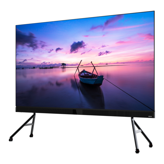
- Page 1 User Manual Newline DV All-in-one Direct View LED Display...
-
Page 2: Table Of Contents
3.3.1 Home Screen ..............................27 3.3.2 System Settings .............................29 4. Maintenance ..............................34 4.1 Precautions ................................34 4.2 LED Display Panel Maintenance ........................34 4.3 LED Display Panel Cleaning ..........................37 4.4 Common Fault Analysis ............................ 37 Newline Interactive Inc newline-interactive.com... - Page 3 5. Transportation and Delivery ........................38 5.1 Transportation ................................38 5.2 Storage ..................................38 5.3 Unpacking ................................38 6. Warranty ................................39 7. Recycling of Discarded Goods ........................39 Newline Interactive Inc newline-interactive.com...
-
Page 4: Safety Instructions
DO NOT place fire or any device that gives off high heat around the display.。 Please use original newline accessories. If you need to use self purchased accessories, please consult customer service. Arrange professional personnel to inspect the screen regularly. -
Page 5: Safety Code
Make sure to take safety measures for grounding the equipment. Warning Signs Preventive measures: For your personal safety and to avoid unnecessary property damage, it is important to pay attention to the prompts in this manual. The reminder for personal safety is indicated Newline Interactive Inc newline-interactive.com... -
Page 6: Documentation
This article is applicable to newline LED all-in-one Direct View LED Display. Copyright Notice Newline reserves the right to make changes to this product manual without prior notice. We are not responsible for any direct, indirect, intentional or unintentional damages or hidden dangers caused by not following the product manual for installation or improper use. -
Page 7: Product Overview
Product Rear 1.2. Product and Accessories All-in-one direct view display Remote control Power cable HDMI cable Maintenance tools LED spare panel Note: The above product accessories are for reference only, and the specific configuration shall prevail. Newline Interactive Inc newline-interactive.com... -
Page 8: Product Introduction
Power supply Sound bar Installing control components Base Support structure, only for standing mode Caster Moving parts, only for standing mode Loudspeaker Playing sound Left cover plate Protective Mid cover plate Protective Right cover plate Protective Newline Interactive Inc newline-interactive.com... -
Page 9: Keys And Interfaces Introduction
Used for connecting to USB device Power light Used to indicate the working status Used for connecting to 3.5mm audio output 9/18 3.5mm output interface devices SPDIF output interface Used for connecting to fiber optic speaker Newline Interactive Inc newline-interactive.com... -
Page 10: Remote Control Introduction
USB Bluetooth transceiver: Before using the remote control, it is necessary to ensure that the USB Bluetooth transceiver is correctly installed on the all-in-one USB interface; After installation, the remote control can be used normally. Newline Interactive Inc newline-interactive.com... -
Page 11: Installation Guide
When moving the cabinet, please do not touch the LED and take anti-static measures to prevent static electricity from damaging the LED or IC device. Please be careful to prevent the lamp surface from colliding or being compressed. Newline Interactive Inc newline-interactive.com... -
Page 12: Installation Dimensions
2.3.1 DV Pedestal installation 1. Open the package of the support structure. 2. Remove the box contents. 3. Connect the two upper beams together by the A1(4X) screw, Notice that the direction of two beams, as below: Newline Interactive Inc newline-interactive.com... - Page 13 A1(4x) A2(4x) 4. Follow the same steps, connect the low beams together, as below: lower beam A2(4x) A1(4x) 5. Assembly the right side and left side of “A“ shape stand with the lower beams Newline Interactive Inc newline-interactive.com...
- Page 14 A7(2x) 6. Connect the right and left upright with the “A”shape stand as below: A6(6x) 7. Connect the upper beam to the right and left castor bases, as shown below: Newline Interactive Inc newline-interactive.com...
-
Page 15: Cabinet Frame And Sound Bar Installation
1). Open the package of cabinet frame and sound bar and remove the contents. 2). Assemble the upper and lower cabinet rack beams 3). Attach the T shape junction plate to the upper rack beam. Notice that the direction of T shape plate. A3(8x) Newline Interactive Inc newline-interactive.com... - Page 16 4). Attach the T shaped junction plate to the lower rack beam. Notice the direction of T shape plate. 5). Connect the right and left vertical bar with the rack beams. A4(24x) 6). Repeat the same steps to connect the middle bar with the rack beams. A4(12x) Newline Interactive Inc newline-interactive.com...
- Page 17 1). Lay down the right and left sound bar before you begin to assemble. 2). Connect the two sound bars with the rectangle connection plate, joining the two halves with the screws. As shown below: A1(2x) A5(8x) A1(4x) Newline Interactive Inc newline-interactive.com...
-
Page 18: Cabinet Installation
3). Remove the middle “C” cabinet from the box first. Notice that on the back of each cabinet there are two stepped screws towards the top. The arrows on the front of the cabinets should be pointing up. Newline Interactive Inc newline-interactive.com... - Page 19 7). Repeat the process with cabinet A, install to the left of cabinet B 8). Repeat the process with cabinet D, install to the right of cabinet C. 9). Repeat the process with cabinet E, install to the left of cabinet D. Newline Interactive Inc newline-interactive.com...
- Page 20 150 inches for example Newline Interactive Inc newline-interactive.com...
- Page 21 12). Attach the 2 pin connection from the soundbar to the cabinet A - IN connection. Then use the single provided 2 pin cables to connect from cabinet A - OUT to cabinet B - IN, Newline Interactive Inc newline-interactive.com...
- Page 22 E - IN. For each cabinet, connect the red wire to the 24v connection point, the black wire to the ground point and the CAT5 connection point. 2 pin cable connection Red and black cable connection Newline Interactive Inc newline-interactive.com...
- Page 23 13). Use the provided hardware to attach the left and right upper borders across the cabinets. A 9 ( 1 2 x ) Each cabinet frame is labeled with module position labels. Staff can quickly identify the module position through tags, as shown in the following figure. Newline Interactive Inc newline-interactive.com...
- Page 24 The number starts from the top left corner of the front and is written in a Z-shape, as shown below. 120 inches: 32 modules/backboards; 150 inches: 40 modules/backboard; 180 inches: 48 modules/backboards. Newline Interactive Inc newline-interactive.com...
- Page 25 Then adjust the magnetic standoffs with a small Philips screw driver to set the depth or height. 4) Attach the cover of the soundbar and then connect power cables to the rear of the soundbar. Newline Interactive Inc newline-interactive.com...
-
Page 26: Function Introduction
1.Connect the HDMI interface of the computer to the HDMI IN interface of the display using an HDMI cable; 2.Use the panel key or remote control to switch channels and switch the display to the HDMI channel. Newline Interactive Inc newline-interactive.com... -
Page 27: Usb Connecting
3.2.3 Audio Output Connection Connection instructions: 1.Connect the 3.5mm audio output port with the external audio devices such as power amplifiers and loudspeakers; 2.The output volume can be adjusted through the panel volume button or remote control. Newline Interactive Inc newline-interactive.com... -
Page 28: System Introduction
1.Video source: When the video source is connected to the all-in-one machine, you can click on the signal source and select the channel HDMI based on the actual connected signal source to display the video image. Newline Interactive Inc newline-interactive.com... - Page 29 2.Settings: Click the settings icon to enter the settings page, and adjust the corresponding items according to the needs, including network, display effects, sound, general, system, and other information viewing and settings. 3. More applications: Enter more applications and select corresponding functions based on actual needs. Newline Interactive Inc newline-interactive.com...
-
Page 30: System Settings
Explanation: The Bluetooth of the all-in-one machine is a Bluetooth host and can only send files to the connected device in one direction. 2. Display Settings "Display Settings": It is possible to choose different display modes and adjust brightness/contrast/saturation/manual or automatic color temperature Newline Interactive Inc newline-interactive.com... - Page 31 3. Sound settings Sound Settings: Ability to adjust playback volume. When there is a different priority between the external speaker and the 3.5mm speaker, the 3.5mm audio interface output can be forcibly selected. Newline Interactive Inc newline-interactive.com...
- Page 32 4. General settings General settings can be used for program management, time and date, language, wallpaper, and other settings. Explanation: The built-in program of the Android system cannot be uninstalled. Newline Interactive Inc newline-interactive.com...
- Page 33 Newline Interactive Inc newline-interactive.com...
- Page 34 Newline Interactive Inc newline-interactive.com...
-
Page 35: Maintenance
This product supports the front maintenance tool for the modules panel, as shown in the following figure. Serial Items Description Ensure good sealing Suction cup rubber ring Newline Interactive Inc newline-interactive.com... - Page 36 Hold the module with one hand to prevent it from falling off. Make sure that the module does not touch the adjacent lamp board when pulling out, so as to avoid collision and damage to the lamp bead. Newline Interactive Inc newline-interactive.com...
- Page 37 Step 4: After moving the module to the safe plane, press the switch key. At this time, the switch identifier O faces down. At this time, the adsorption force is removed and maintain modules, HUB board, receiving card. Newline Interactive Inc newline-interactive.com...
-
Page 38: Led Display Panel Cleaning
No video signal Signal source mismatch match and match the signal source. output after connecting Check for poor contact and correct HDMI cable HDMI cable damaged direction of the HDMI cable, and replace the HDMI cable. Newline Interactive Inc newline-interactive.com... -
Page 39: Transportation And Delivery
2. Keep your documents in a safe place. This document is required for commissioning the device. It is also needed when presenting the equipment for debugging, and it is part of the equipment. and is part of the device. Newline Interactive Inc newline-interactive.com... -
Page 40: Warranty
It is recommended that consumers comply with local safety and environmental regulations and hand over the product to a local distributor or qualified waste recycling department for disposal when it is abandoned, in order to avoid environmental pollution and improve the material recycling rate. Newline Interactive Inc newline-interactive.com...
Need help?
Do you have a question about the DV Series and is the answer not in the manual?
Questions and answers