Table of Contents
Advertisement
Quick Links
Advertisement
Table of Contents

Subscribe to Our Youtube Channel
Related Manuals for NewLine DV Series


Summary of Contents for NewLine DV Series
- Page 1 MANUAL Newline DV Series...
-
Page 2: Table Of Contents
Contents Safety guides Important warnings Copyright warning & caution Qualified professional Safety regulations Document description Agreement Description Packing Overview Features Control system(optional) Product and accessories Interface Product introduction Software Installation guide Precautions Installation dimensions Installation steps Transportation and delivery Transportation 2.3.1 Base-installation 2.3.2... -
Page 3: Safety Guides
(the LED display cannot be turned off for a long time). If the display has not been used for more Please connect the power cord and/or the network cable as recommended by Newline. than 3 days under the condition of high ambient humidity, it is necessary to check whether there is moisture on the surface before lighting up;... -
Page 4: Warning & Caution
Indicates that minor personal injury may result if proper protective measures are not taken. NOTICE: Indicates that unintended consequences may result if the proper protective measures are not In this document, “display” or “product” refers to the LED display of DV series. taken. QUALIFIED PROFESSIONAL... -
Page 5: Overview
1-1.5 Overview 1. OVERVIEW Display system with stable performance, exquisite picture and high definition AI smart adjustment, energy saving and environmental protection, supporting multiple equipment projection and control with rich interfaces; Self-developed image quality engine 1.0; Power cord Front Maintenance Tools Remote control The modular design of the structure enables quick disassembly and assembly, which is convenient and efficient to operate, and ultra-thin and ultra-light. -
Page 6: Installation Guide
2-2.4 Installation guide When moving the cabinet, please do not touch the LED and take anti-static measures to prevent Description Remarks static electricity from damaging the LED or IC device; Frame Installing the display panel Do not leave screws, nuts and other metals in the box during the installation process to prevent short circuit when the screen is working;... -
Page 7: Base-Installation
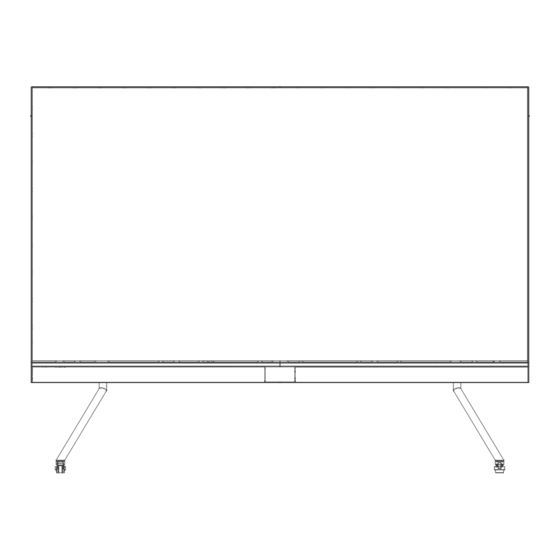
2-2.4 Installation Guide Remarks Model No DV-12023W 3344 2633.5 19.8 2020 Cross recessed pan head Cross recessed cheese DV-15023W Socket head cap screw head screws(M4) screws(M5) (M5、M8) DV-18023W 4010 2394.56 19.8 Cross screwdriver Cross screwdriver (diameter 6.3mm) (diameter 3.5mm) Step 1: install the upper and lower beams of the base. Use four M4 * 12 cross countersunk screws Note: W1 and H1 are the installation dimensions of the Stand-alone LED display, W2 and H2 are the installation dimensions at the bottom of the beams and four M5 * 12 cross countersunk screws on the side to tighten and... - Page 8 2-2.4 Installation Guide Step 2: install the base. Insert the connecting shaft downward into the base, and fix the base, connecting shaft and lower beam with four M8 * 50 screws (Note: the side of the beam with M5 screw hole shall face to side A, while the M4 screw hole of the beam shall face down, and the direction of the beam and A-type support shall not be reversed).
- Page 9 2-2.4 Installation Guide Step 6: assemble the stud-link assembly of the back-mounted rack. Fix the upper and lower back-mounted racks and the three middle vertical bar assembly on the T-shaped junction Screw plate with M5 * 12 countersunk screws, fix and connect the sheet metal corner connector with Screw Upper beam the upper and lower back-mounted racks with M5x10 cross recessed pan head screw, and...
- Page 10 2-2.4 Installation Guide Step 9: fix the lower beam assembly and the back-mounted rack assembly. A total of six M5 * 75 screws U-shaped groove are passed through 1, 2 and 3 in the back-mounted rack to fix with the screw hole of M5 connecting block in the lower beam (Note: do not press the power cord and data line).
- Page 11 2-2.4 Installation Guide Step 11: install the first row of cabinet frame. Insert the cabinet frame with right border installed with HUB Step 13: refer to step 12 to install the remaining cabinet frame in turn (Note: the first column on the left is board into the U-shaped groove of back-mounted rack through stepped screw from right to left until the the cabinet frame with left border).
- Page 12 2-2.4 Installation Guide Step 15: connect the two adjacent columns of cabinet frames with three different magnet supports, Upper border (left) Upper border (right) and fix them with M4 * 10 cross recessed pan head tapping screws. At the same time, adjust the flatness of the cabinet frame during the installation process.
- Page 13 2-2.4 Installation Guide Step 19: connect the signal line of Stand-alone LED display. The signal line of Stand-alone LED Step 21: install the breathing LED board in the middle of the lower beam. Connect the flat cables with display is shown in the figure below. the breathing LED board, and then attach the breathing LED board in the middle of the lower beam.
-
Page 14: Wall-Mounted Installation
2-2.4 Installation Guide Precautions: Step 1: assemble the upper and lower back-mounted rack beams. Use four M5 * 12 cross recessed countersunk head screws to fix the T-shaped junction plate and the back-mounted rack beams. 1. Please do not power on the cabinet during the connection of power cords and network cables to prevent the risk of electric shock 2. -
Page 15: Segment Gap Adjustment Of Display Module
2-2.4 Installation Guide 2.4 Segment Gap Adjustment of Display Module Step 3: install the back-mounted rack assembly. Fix the stud-link wall-mounted beam assembly on the wall with 16 M8 screws (or expansion screws). (Note: when installing 120-inch display, the wall can bear at least 290kg;... -
Page 16: Maintenance
3-3.4 Maintenance 3. MAINTENANCE 3.1 Precautions 1. Before the maintenance of LED display, the power supply of the display must be cut off the power of the screen body during installation and maintenance to prevent electric shock and injury, and avoid short circuit of the live parts of the PCB board against the metal frame;... -
Page 17: Cleaning
3-3.4 Maintenance The main process of front display maintenance is as follows: Step 4: move the LED panel to the safety plane, release the vacuum button, and set the switch to "O", that is, release the adsorption force and remove the tools. At this time, the LED panel, HUB board and control card can be maintained. -
Page 18: Troubleshooting
3-3.4 Maintenance Troubleshooting FAULT ANALYSIS SOLUTION FAULT ANALYSIS SOLUTION Check if the display is Power on. 1 ) Resend the product configura - powered on. tion parameters in the existing Project file. Please contact cus- 1 ) Data line is not connected prop - Check the computer settings to tomer service staff for details. -
Page 19: Packing
Packing Methods 4. PACKING METHODS Load-bearing carton The frame, A-type base and LED panel of Stand-alone LED display are packed separately. One cabinet frame load-bearing carton can pack all the cabinet frames of Stand-alone LED display , and the packing methods are as follows: Carton Pearl cotton Pearl cotton corner guard... -
Page 20: Control System(Optional)
5- 5.2 Control System 5.2 Software 5. CONTROL SYSTEM(optional) To be updated. 5.1 interface The interfaces of Stand-alone LED display are shown in the figure below: Interface Description Interface 1 Gigabit Ethernet port, used to connect external network to realize network Interface 2 interconnection USB3.0 interface, which can be used to access mouse, keyboard, U disk,... - Page 21 39/40...
-
Page 22: Transportation And Delivery
6-6.3 Transportation and Delivery 6. TRANSPORTATION AND DELIVERY 6.1 Transportation Packaged products are suitable for air, sea and land transportation. It is not allowed to be loaded in an open cabin or compartment during long-distance transportation. It is not allowed to be stored in an open storage during transshipment en route. It is not allowed to transfer together with flammable, explosive or perishable goods in a same vehicle (or other means of transport) in the transportation process. -
Page 23: Unpacking
The product should not be exposed to the installation site under construction for a long time after unpacking. Newline is not responsible for any personal, property or other damages caused by the failure to follow contents of this document, including but not limited to instructions, procedures, specifications, warnings, etc.
Need help?
Do you have a question about the DV Series and is the answer not in the manual?
Questions and answers