Table of Contents
Advertisement
Quick Links
Advertisement
Table of Contents

Related Manuals for NewLine DV Pro


Summary of Contents for NewLine DV Pro
- Page 1 USER MANUAL DV Pro / DV Premier LED Display...
-
Page 3: Table Of Contents
2.3.1 Stacking Installation ........................12 2.3.2 Wall-mounted..........................18 2.4. Segment Gap Adjustment of Display Module ................. 25 3. Maintenance ..........................27 3.1. Precautions ............................27 3.2. Screen maintenance ........................27 3.2.1 Maintenance tool ........................27 3.2.2 Maintenance process ........................ 29 Newline Interactive Inc newline-interactive.com... - Page 4 3.4. Common Fault Analysis ........................33 4. Unpacking The LED Cabinet ......................35 4.1. Packing Method ..........................35 4.2. Unpacking method .......................... 37 Transportation And Delivery ......................38 Transportation ............................38 Delivery ..............................38 Equipment unpacking ..........................39 Warranty ............................39 Newline Interactive Inc newline-interactive.com...
-
Page 5: Safety Guides
DO NOT repeatedly bend or move the power cable or data cable frequently to avoid damaging the cable and causing electric shock or fire. Please connect the power cable and/or the data cable as recommended by newline. Please arrange, tie and fix the power cable and data cable orderly after the installation, and separate ... -
Page 6: Important Warnings
Before installation, ensure that the operating voltage of the display is suitable for the local grid voltage. Copyright Notice • newline reserves the right to make changes to this product manual without prior notice. We are Newline Interactive Inc newline-interactive.com... -
Page 7: Warning Signs
• is the registered trademark of newline. The ownership of other trademarks involved in this manual belongs to the corresponding product manufacturers。 Warning Signs... -
Page 8: Documentation
Scope of application of this document: This article is applicable to Newline DV Pro and DV Premier series product. Agreement In this document, the term "LED display" or "product' refers specifically to the DV Pro or DV Premier series fixed-mounted LED display. Newline Interactive Inc... -
Page 9: Product Overview
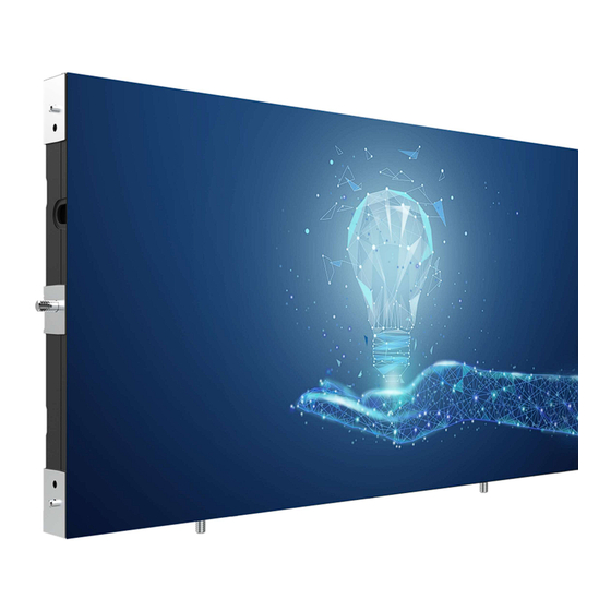
Product Overview • The indoor DV Pro/Premier Series display is modular in design and can be used for indoor fixed installations. • The DV Pro/Premier series has the characteristics of ultra-light, ultra-thin, fast installation and maintenance, convenient operation, space saving. It can be widely used in conference rooms, monitoring and command centers, television stations, commercial advertising and other places. -
Page 10: Led Cabinet Instruction
Adjustment device, used to adjust the flatness from hole the back. Positioning device, used for quick positioning Right locating pin between left and left cabinets. Fixed structure, used to fix with the screen mounting Mounting Hole structure. Nameplate Show information on manufacturer's trademark, Newline Interactive Inc newline-interactive.com... - Page 11 Right spacing Adjustment device, used to increase the gap adjustment hole between the left and right cabinets. Left and right fixing Fixed device, used to connect and fix the left and holes right cabinets. Newline Interactive Inc newline-interactive.com...
-
Page 12: Installation Guide
LED or IC device. If the LED cabinet needs to be temporarily placed somewhere before installing the display, please ensure the LED face is oriented upwards. If it is necessary to place the LED face downwards, please Newline Interactive Inc newline-interactive.com... -
Page 13: Installation Dimensions
1.Tile (LED surface down - Anti-static foam) 2.Tile(LED surface up) 3. Lean against the wall 4. Suspend with a holder 5. DO NOT stack heavy objects on 6. Prevent objects from falling the cabinet. and bumping the LED surface. 2.2. Installation Dimensions Newline Interactive Inc newline-interactive.com... -
Page 14: Installation Steps
Steadily place the first cabinet on the horizontal beam base, then proceed to secure the cabinet to the mounting bracket using screws. (Please note that the mounting bracket structure provided is for reference only, and the actual engineering application scheme should be followed.) Newline Interactive Inc newline-interactive.com... - Page 15 Close the two cabinets together, then proceed to tighten the upper and lower M8 *30 screws. Step 3: Fix the second cabinet to the mounting bracket (Same as Step 1). Newline Interactive Inc newline-interactive.com...
- Page 16 Step 5: Install the first cabinet in the second row. Align the pin hole of the upper cabinet with the locating pin of the lower cabinet and place it on the lower cabinet, and tighten the left and right M8 * 30 screws. Newline Interactive Inc newline-interactive.com...
- Page 17 Step 8: Connect the power cable and data cables between cabinets. The external power cable and data cables can enter the screen from the bottom or rear of the display. Please select the appropriate routing mode according to the actual engineering application. Newline Interactive Inc newline-interactive.com...
- Page 18 The example of data cable connection between cabinets is as follows. For practical engineering applications, please connect the data cable according to the data cable connection scheme in the system diagram. Newline Interactive Inc newline-interactive.com...
- Page 19 Step 9: Install the module. First connect the FFC cable and DC power cable, then align the stainless iron on the module with the magnet on the cabinet, and then attach the module to the cabinet. Newline Interactive Inc newline-interactive.com...
-
Page 20: Wall-Mounted
Step 1: Install the first wall-mounted beam. Secure the wall hanging beam on the wall using M8 bolts (or expansion screws). Ensure that the wall-mounted beam is horizontally level and that the hanging holes are facing upward. Newline Interactive Inc newline-interactive.com... - Page 21 Step 3: Install the second wall-mounted beam. Place the second wall-mounted beam on the gauges, and fix the second wall-mounted beam with M8 bolt (or expansion screw). The gauges are used to ensure the location between two wall-mounted beams. Newline Interactive Inc newline-interactive.com...
- Page 22 Note: If the wall mounted gauge is 3 times the height of the cabinet, the upper and lower 5 cabinet frames need to be spliced together for installation. Step 6: Install wall hanging screws on the back of the cabinet frame. Newline Interactive Inc newline-interactive.com...
- Page 23 Step 7: Hang the first column cabinet frame components on the wall-mounted beam. Move the cabinet frame components from top to bottom along the wall-mounted holes, ensuring the screws for wall hanging clip into the wall-mounted holes. Newline Interactive Inc newline-interactive.com...
- Page 24 Step 8: Move the cabinet frame to the endpoint. Move the cabinet frame so that the side of the cabinet frame is flush with the side of the wall mounted crossbeam. Newline Interactive Inc newline-interactive.com...
- Page 25 After the two columns of cabinet frames are tightly attached, use M8 * 30 screws to lock and connect the first and second column cabinet frames. During this process, be careful to prevent the framework from being misaligned. Newline Interactive Inc newline-interactive.com...
- Page 26 2.The voltage of this product is 100 ~ 240V, 50 / 60Hz. Please use the product within the specified power range to avoid fire or electric shock. 3.The power cable cannot be overloaded. 4.Please tighten the screws of the power cable to prevent the product from burning due to the Newline Interactive Inc newline-interactive.com...
-
Page 27: Segment Gap Adjustment Of Display Module
2.5 Phillips screwdriver to rotate the magnet set and adjust the magnet up and down during front maintenance. 六角扳手 When adjusting the magnet set from rear of display, use a straight screwdriver to rotate the magnet set Newline Interactive Inc newline-interactive.com... - Page 28 Newline Interactive Inc newline-interactive.com...
-
Page 29: Maintenance
3.2. Screen maintenance aintenance tool 3.2.1 M This product supports front module maintenance. The tools required for front maintenance are vacuum front maintenance tools, as shown below:: Newline Interactive Inc newline-interactive.com... - Page 30 For drawing the sucker ON/OFF Switching power supply: """ on; "o" off Battery module Power supply for fans Charge socket For battery charging Sucker Seal between tools and LED module Rubber ring Ensure good sealing of sucker Newline Interactive Inc newline-interactive.com...
-
Page 31: Maintenance Process
40%. Step 3: Hold the handle and the draw bar with both hands at the same time, place the maintenance tools in the center position of the module and close to the surface of the module. Newline Interactive Inc newline-interactive.com... - Page 32 Step 4: Gently touch the fan button to [1] to operate the vacuum suction maintenance tool at low power. Step 5: Hold the handle with both hands, wait about 3s, pull up the handle, make the handle from the position in state 1 to the position in state 2, and pull out the module. Newline Interactive Inc newline-interactive.com...
-
Page 33: Cleaning
Step 7: After removing the module, maintenance can be performed on the lamp panel, internal power supply, and control card. 3.3. Cleaning During the use of the product, dust or other stains may adhere to the surface of the cabinet, affecting Newline Interactive Inc newline-interactive.com... - Page 34 1. Do not use industrial grease cleaning agent in the cleaning process, only use materials or chemicals that have no reaction, corrosion, damage, or trace. 2. Do not use scrubbing brush. 3. Take anti-static measures to prevent the static electricity from damaging the LED. Newline Interactive Inc newline-interactive.com...
-
Page 35: Common Fault Analysis
2. Check the external power cable. light is flashing abnormally or black 3. Replace the switch power supply. constantly on. 4. Replace the product system scanning card. 3. The data cable is not connected properly. 4.The power cable is not Newline Interactive Inc newline-interactive.com... - Page 36 LED module repair service. 3.Module's color correction data is failure 2.Replace the HUB card and consult lost. the customer service for professional 4. Data port of HUB card is of repair service. poor contact Newline Interactive Inc newline-interactive.com...
-
Page 37: Unpacking The Led Cabinet
Three frame components are bundled together by ropes, and the frame packaging method is as follows: Place the bundled frame components in a steel edged wooden box, with 42 frame components packed in one wooden box. The placement and packaging methods are as follows: Newline Interactive Inc newline-interactive.com... - Page 38 Note: If the module is a GOB or MIP, the anti-static film needs to be replaced with 2mm pearl cotton. Place the packaged module above the frame inside the wooden box, with a total of 12 packages in 2 Newline Interactive Inc newline-interactive.com...
-
Page 39: Unpacking Method
Remove the carton and open it to extract the cabinet and module. Attention: When dismantling the module packaging, anti-static measures should be taken to prevent static electricity from damaging the lamp beads. Newline Interactive Inc newline-interactive.com... -
Page 40: Transportation And Delivery
If condensation has formed on the device, please wait at least 12 hours before connecting the device. 2. When the product is damp, please keep the storage environment ventilated. After drying the product, put it back into the original packaging box for storage. 3. Unpacking and inspection of delivered equipment. Newline Interactive Inc newline-interactive.com... -
Page 41: Equipment Unpacking
Other faults caused by reasons other than normal wear and tear (normal wear and tear refers to the wear and tear of the product itself, components, and software systems that occur under the premise of complying with this document); Newline Interactive Inc newline-interactive.com... - Page 42 3.newline Company shall not be liable for any personal, property, or other losses caused by failure to comply with the contents of this document, including but not limited to guidance, steps, specifications, warnings, etc. Newline Interactive Inc newline-interactive.com...
Need help?
Do you have a question about the DV Pro and is the answer not in the manual?
Questions and answers