Moxa Technologies NPort S8000 Series Quick Start Manual
Hide thumbs
Also See for NPort S8000 Series:
- User manual (168 pages) ,
- Quick installation manual (6 pages)
Table of Contents
Advertisement
Quick Links
Download this manual
See also:
User Manual
NPort S8000 Series
Quick Installation Guide
Second Edition, June 2014
Overview
The Moxa NPort S8000 series fully integrates an industrial serial
device server and redundant managed Ethernet switch into a
single device, making it easy to enable your serial devices to
operate over a network, and connect Ethernet-enabled devices in
industrial field applications.
Package Checklist
Before installing the NPort S8000, verify that the package contains
the following items:
•
1 NPort S8000 combo switch / serial device server
•
CBL-RJ45F9-150 cable
•
2 RJ45 dust cover packs
•
Documentation and software CD
•
Quick installation guide
•
Warranty card
Optional Accessories (must be ordered separately)
•
Wall mounting kit
Note: Please notify your sales representative if any of the above
items are missing or damaged.
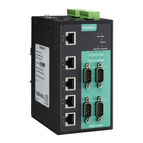
Hardware Introduction
The NPort S8455 integrates 2 fiber ports, 3 Ethernet ports, and 4
male DB9 ports for the RS-232/422/485 serial port.
The NPort S8458 integrates 4 fiber ports, 4 Ethernet ports, and 4
male DB9 ports for the RS-232/422/485 serial port.
Reset Button—Hold the Reset button for 5 sec to load factory
default settings: Use a pointed object, such as a straightened
paper clip or toothpick, to press the reset button. This will cause
the Ready LED to blink on and off. The factory defaults will be
loaded once the Ready LED stops blinking (after about 5 seconds).
At this point, you should release the reset button.
LED Indicators—The NPort S8000's front panel contains some
LED indicators, as described in the following table.
P/N: 1802084550020
– 1 –
Type
Color
Meaning
PW 1
Green
Power 1 input
PW 2
Green
Power 2 input
Ready
Red
Steady On: Power is on and the NPort is
booting up.
Blinking: Indicates an LAN IP conflict, or
DHCP or BOOTP server did not respond
properly.
Green
Steady On: Power is on and the NPort is
functioning normally.
Blinking: The device server has been located
by the Administrator's location function.
Off
Power is off, or power error condition exists.
Master
Green
When the NPort is the Master of this Turbo
Ring.
Blinking
When the NPort is the Ring Master of this
Turbo Ring and the Turbo Ring is
disconnected.
Coupler
Green
When the NPort enables the coupling
function to form a backup path
Serial Port
Green
The serial port is transmitting data.
TX
Serial Port
Yellow
The serial port is receiving data.
RX
Link (FX) Green
The FX port's 100 Mbps is active
Blinking
Data is being transmitted/received at 100
Mbps
Link
Green
The 100 Mbps Ethernet connection is active.
Yellow
The 10 Mbps Ethernet connection is active.
Hardware Installation Procedure
STEP 1: After removing the NPort S8000 from the box, first attach
the power adaptor.
STEP 2: Connect the NPort S8000 to a network. Use a standard
straight-through Ethernet cable to connect to a hub or switch.
When setting up or testing the NPort S8000, you might find it
convenient to connect directly to your computer's Ethernet port. In
this case, use a cross-over Ethernet cable.
STEP 3: Connect the NPort S8000's serial port to a serial device.
STEP 4: Mount the NPort S8000 to either a wall or DIN-Rail, as
described below.
Wall Mounting (optional)
In high vibration environments, we suggest using the NPort
S8000's wall mount kit to fix. The installation procedure iss
described below.
STEP 1: Remove the aluminum DIN-Rail attachment plate from
the NPort S8000's rear panel, and then attach the wall mount
plates with M3 screws.
– 2 –
STEP 2: Four screws are required. Use the NPort
S8000, with wall mount plates attached, as a
guide to mark the correct locations of the 4
screws. The heads of the screws should be less
than 6.0 mm in diameter, and the shafts should be
less than 3.5 mm in diameter.
NOTE Before tightening the screws into the wall, make sure the
screw head and shank size are suitable by inserting one of
the screws into one of the keyhole-shaped apertures of the
wall mounting plates.
Do not screw the screws in completely—leave about 2 mm to allow
room for sliding the wall mount panel between the wall and the
screws.
STEP 3: Once the screws are fixed to the wall, insert the four
screw heads through the large parts of the keyhole-shaped
apertures, and then slide the NPort S8000 downwards, as
indicated. Tighten the four screws for added stability.
DIN-Rail Mounting (optional)
DIN-Rail attachments can be purchased separately
to attach the product to a DIN-Rail. When snapping
the attachments to the DIN-Rail, make sure that the
stiff metal springs are at the top.
– 3 –
Advertisement
Table of Contents

Related Manuals for Moxa Technologies NPort S8000 Series


Summary of Contents for Moxa Technologies NPort S8000 Series
-
Page 1: Package Checklist
Overview Blinking: The device server has been located by the Administrator’s location function. The Moxa NPort S8000 series fully integrates an industrial serial Power is off, or power error condition exists. device server and redundant managed Ethernet switch into a... -
Page 2: Specifications
the terminal block receptor. The meaning of the two contacts used Terminal 1 Terminal 2 Turbo Ring DIP Switch Settings to connect the relay contacts is illustrated below. The default setting for each DIP switch is OFF. The The fault circuit will open if following table explains the effect of setting the DIP 1.
Need help?
Do you have a question about the NPort S8000 Series and is the answer not in the manual?
Questions and answers