Table of Contents

Subscribe to Our Youtube Channel
Related Manuals for NPI LPBF-01GX


Summary of Contents for NPI LPBF-01GX
- Page 1 LPBF-01GX AMPLIFIER / FILTER MODULE FOR EPMS SYSTEMS Version 1.5 npi 2016 npi electronic GmbH, Bauhofring 16, D-71732 Tamm, Germany Phone +49 (0)7141-9730230; Fax: +49 (0)7141-9730240 support@npielectronic.com; http://www.npielectronic.com...
-
Page 2: Table Of Contents
EPMS-07, EPMS-E-07 and EPMS-H-07 ..............6 EPMS-07 and EPMS-H-07 ..................6 EPMS-E-07 ........................6 EPMS-03 ........................6 LPBF-01GX Amplifier / Filter Module ................7 3.1. LPBF-01GX Components ................... 7 3.2. System Description ...................... 7 ... -
Page 3: Safety Regulations
(e.g. for diagnosis or treatment of humans), or for any other life-supporting system. npi electronic disclaims any warranties for such purpose. Equipment supplied by npi electronic must be operated only by selected, trained and adequately instructed personnel. -
Page 4: Epms-07 Modular Plug-In System
2. EPMS-07 Modular Plug-In System 2.1. General System Description / Operation The npi EPMS-07 is a modular system for processing of bioelectrical signals in electrophysiology. The system is housed in a 19” rackmount cabinet (3U) has room for up to 7 plug-in units. -
Page 5: Epms-03
Note: The chassis of the PWR-03D is connected to protective earth, and it provides protective earth to the EPMS-E housing if connected. Figure 3: Left: PWR-03D front panel view Right: PWR-03D rear panel view. Note: This power supply is intended to be used with npi EPMS-E systems only. ___________________________________________________________________________ version 1.5 page 5... -
Page 6: System Grounding
LPBF-01GX User Manual ___________________________________________________________________________ 2.7. System Grounding EPMS-07/EPMS-03 The 19" cabinet is grounded by the power cable through the ground pin of the mains connector (= protective earth). In order to avoid ground loops the internal ground is isolated from the protective earth. -
Page 7: Lpbf-01Gx Amplifier / Filter Module
3.2. System Description The LPBF-01GX amplifier/filter is designed for the processing of small bio-electrical signals. The LPBF-01GX is available as plug-in unit for the EPMS-07 plug-in-system. The input voltage range is ±12 V. All inputs and output are BNC-connectors. The unit is equipped with an unipolar input stage with an AC/O/DC switch. The input stage is followed by the offset compensation adjustable with a ten-turn potentiometer. -
Page 8: Description Of The Front Panel And Operation
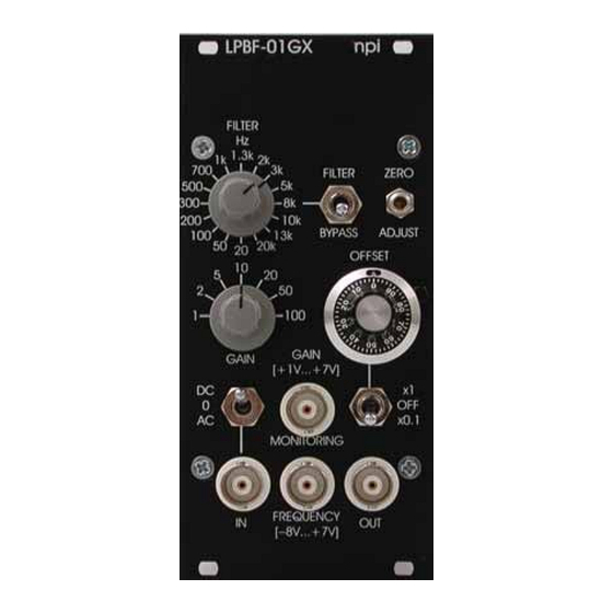
___________________________________________________________________________ 3.4. Description of the Front Panel and Operation Figure 5: front panel view of LPBF-01GX In the following description of the front panel elements each element has a number that is related to that in Figure 5. The number is followed by the name (in uppercase letters) written on the front panel and the type of the element (in lowercase letters). - Page 9 LPBF-01GX User Manual ___________________________________________________________________________ ZERO ADJUST trim pot Trim pot for compensation of amplifier offsets. Tuning is done by setting switch #4 to OFF and trimming any remaining offsets to ZERO OFFSET unit The OFFSET unit consists of (3) OFFSET potentiometer and (4) OFFSET...
- Page 10 LPBF-01GX User Manual ___________________________________________________________________________ INPUT unit The INPUT unit consists of (8) IN connector and (9) AC / 0 / DC input coupling switch (8) IN connector BNC connector to connect the signal to be processed (9) AC / 0 / DC input coupling switch The position of the input coupling switch decides how the input signal is coupled: the input signal is AC coupled with a corner frequency of 0.1 Hz...
-
Page 11: Literature
LPBF-01GX User Manual ___________________________________________________________________________ 4. Literature Kettenmann, H. & Grantyn, R. (eds.) (1992) Practical Electrophysiological Methods, WileyLiss, New York Ogden DC (1994) Microelectrode Techniques. The Plymouth Workshop Handbook Second Edition, The Company of Biologists Limited, Cambridge Tietze, U and Ch. Schenk (1999) Halbleiter-Schaltungstechnik (Semiconductor Techniques) 11.
Need help?
Do you have a question about the LPBF-01GX and is the answer not in the manual?
Questions and answers