Advertisement
Quick Links
Advertisement

Related Manuals for Ford Pro DC Charging Cabinet


Summary of Contents for Ford Pro DC Charging Cabinet
- Page 1 ™ Ford Pro DC Charging Cabinet Installation Manual Revision 1.5...
-
Page 2: Site Recommendations
• Soil compaction degree of 98%. • Maximum land unevenness of 0.25%. • It must not be a direct place of passage so that the load cables do not interrupt the movement of pedestrians or tra c. Ford Pro contact info: chargingsupport@fordpro.com and 1-800-34-FLEET... - Page 3 !)The transverse side of the reinforcement must be able to withstand forces of up to 10kN. Note that the thickness of the slab must be determined from the results of the geotechnical study. See anchor recommendations at the "Anchoring of the equipment" section. !'" Ford Pro contact info: chargingsupport@fordpro.com and 1-800-34-FLEET (,+(.,.0/)!$8),$/!20.11/!K$0L+$+H3/(A+!0$...
- Page 4 Dispenser must also be taken into account. This distance can not exceed 80 m (262.46 ft) with Ethernet communication or 150 m (492.13 ft) with the optical fiber communication, as optional. !(" Ford Pro contact info: chargingsupport@fordpro.com and 1-800-34-FLEET (,+(.,.0/)!$8),$/!20.11/!K$0L+$+H3/(A+!0$...
- Page 5 For both options, it is recommended to use M16 (5/8”) A4-70 stainless screws for high load solicitations, being accepted both expansive anchor bolts and chemical. Please, secure them applying the recommended torque for mechanical connections. !)" Ford Pro contact info: chargingsupport@fordpro.com and 1-800-34-FLEET (,+(.,.0/)!$8),$/!20.11/!K$0L+$+H3/(A+!0$...
- Page 6 Equipment anchoring using the four internal holes, with the following dimensions. ANCHORING DIMENSIONS – OPTION 1 23.6 Option 2 Equipment anchoring using the four external holes, with the following dimensions. ANCHORING DIMENSIONS – OPTION 2 Ø 19.6 37.8 #+" Ford Pro contact info: chargingsupport@fordpro.com and 1-800-34-FLEET (,+(.,.0/)!$8),$/!20.11/!K$0L+$+H3/(A+!0$...
-
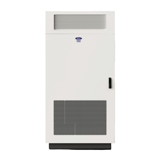
Page 7: Ventilation System
The power cabinet has a forced air ventilation system. The air inlet is located at the bottom of the door and the oulet is at the top. #*" Ford Pro contact info: chargingsupport@fordpro.com and 1-800-34-FLEET (,+(.,.0/)!$8),$/!20.11/!K$0L+$+H3/(A+!0$... - Page 8 !"#$%&'$()*+,$-."/!+0$ ()*+,$+1+-0,)!/-2$ F-!;E4:E4!:;<73!>;887>4B;8D! MV09)<;82):8@+;)73A04+9)98)O01:+41+;-) <OTPL(,#gL'( ./+)93A6+)A+68@)1/8@1)9/+);+7822+4?+?)73A6+)10j+)<8;)9/+):8@+;)73A04+9)98)O01:+41+;-)Z51982+;) 2519)7/881+)9/+)73A6+1)93h04>)0498)78410?+;39084)9/+)2040252)34?)23V0252)?032+9+;=)31)@+66)31)9/+) :3;907563;090+1)8<)9/+):;8P+79[) 318018(03=!2(4100>C( ^:<mb:<W_( 2!<3@@!5: <)6>!( @;5;@1@( @)l;@1@( 9>)5:( :;)@!8!2( :;)@!8!2( 4!<8;35( 56#.D IK)22|)^XH&)T(U_) YK&)^Jy_) J`)22)^$-&G)04-_) XK)22)^$-X%)04-_) 56#.E $J&)22|)^]H&) YK&)^Jy_) J`)22)^$-&G)04-_) XK)22)^$-X%)04-_) T(U_) 56#/- $%K)22|) YK&)^Jy_) J`)22)^$-&G)04-_) XK)22)^$-X%)04-_) ^X&&YZY_) 56#/H $%K)22|) YK&)^Jy_) J`)22)^$-&G)04-_) XK)22)^$-X%)04-_) ^X&&YZY_) 56#/7 $%K)22|)
Need help?
Do you have a question about the Pro DC Charging Cabinet and is the answer not in the manual?
Questions and answers