Miranda picoLink Series Manual To Installation And Operation
Hd serial digital component analog video converter
Hide thumbs
Also See for picoLink Series:
- Manual to installation and operation (16 pages) ,
- Manual to installation and operation (15 pages) ,
- Manual to installation and operation (11 pages)
Table of Contents
Advertisement
Quick Links
picoLink Series
SDM-871p
Guide to Installation
and Operation
M277-9900-101
Miranda Technologies Inc.
Specifications may be subject to change.
Technologies inc.
3499 Douglas-B.-Floreani
St-Laurent, Que ´bec, Canada H4S 1Y6
Copyright 2002
Printed in Canada
August 2002
Miranda
Tel. 514-333-1772
Fax. 514-333-9828
www.miranda.com
HD Serial Digital
Component Analog
Video Converter
Advertisement
Table of Contents

Subscribe to Our Youtube Channel
Related Manuals for Miranda picoLink Series


Summary of Contents for Miranda picoLink Series
- Page 1 Series HD Serial Digital Component Analog SDM-871p Video Converter Guide to Installation and Operation M277-9900-101 Copyright 2002 Miranda Technologies Inc. Specifications may be subject to change. Printed in Canada August 2002 Miranda Technologies inc. 3499 Douglas-B.-Floreani St-Laurent, Que ´bec, Canada H4S 1Y6 Tel.
-
Page 2: Warranty Policies
Miranda, at its sole dis- cretion. In no event shall Miranda Technologies Inc. be liable for any incidental or consequential damages, including loss of profits. - Page 3 SDM-871p - Guide to Installation and Operation for the delivery of the loaner or exchange products or parts. Freight and insurance charges for the return of the defective product or part will also be paid by Miranda Technologies. Out-Of-Warranty Repair Policy Miranda will repair equipment which is out of Warranty.
- Page 4 SDM-871p - Guide to Installation and Operation How to contact us: Head Office Miranda Europe Miranda Technologies Inc. 222, 226 Rue De Rosny 3499 Douglas-B.-Floreani 93100 Montreuil St. Laurent (Montreal), Que. H4S 1Y6 France Canada +1 (514) 333-1772 +33 1 55 86 87 88...
- Page 5 SDM-871p - Guide to Installation and Operation...
-
Page 6: Table Of Contents
SDM-871p - Guide to Installation and Operation Contents page 1 SDM-871p HD Serial Digital to Component Analog Video Converter ............1 1.1 Introduction............... 1 1.2 Features..............1 2 Overall View ..............3 3 Installation ..............5 3.1 Power Supply............5 3.2 HD Serial Digital Input with Active Loop-through..5 3.3 HD CAV Output............6 4 Operation ................ - Page 7 SDM-871p - Guide to Installation and Operation...
-
Page 8: Sdm-871P Hd Serial Digital To Component Analog Video Converter
SDM-871p - Guide to Installation and Operation 1 SDM-871p HD Serial Digital to Component Analog Video Converter 1.1 Introduction The SDM-871p is a miniature stand-alone high definition DAC converting serial digital HDTV (SMPTE 292M) to high definition component analog (Y/Pb/Pr or GBR user selectable). The SDM- 871p provides automatic input scan rate detection and supports a wide variety of input formats including 720p, 1035i and 1080i standards at multiple frame rates. - Page 9 SDM-871p - Guide to Installation and Operation...
-
Page 10: Overall View
SDM-871p - Guide to Installation and Operation 2 Overall view The figure below represents the SDM-871p. The high definition digital video source is connected to the BNC input connector. A reclocked signal is supplied by the active loop-through BNC con- nector. - Page 11 SDM-871p - Guide to Installation and Operation...
-
Page 12: Installation
SDM-871p - Guide to Installation and Operation 3 Installation 3.1 Power Supply The power supplies LKS-WSA and LKS-WSE, for 110V and 220V operation respectively, are used to power the SDM-871p. Each power supply provides a regulated +5VDC@1A power source. Plug the power supply into a wall or power bar outlet. The SDM- 871p uses a mini XLR-3 connector for its power needs;... -
Page 13: Hd Cav Output
SDM-871p - Guide to Installation and Operation 3.3 HD CAV Output The high definition component output signal is provided by the HD-15S (female) labeled ANALOG OUT. The high definition CAV output format is automatically selected according to the input signal; for a complete list of the output formats and related SMPTE standards refer to section 5 Specifications. -
Page 14: Operation
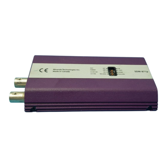
SDM-871p - Guide to Installation and Operation 4 Operation 4.1 Switch Settings Figure 4.1 outlines the slide switch functions. Figure 4.1 SDM-871p Underside TEST Miranda Technologies Inc. FORMAT YPbPr SDM-871p Made in Canada CS ON CAV NONE CS TYPE TRI LEVEL... -
Page 15: Status Led
SDM-871p - Guide to Installation and Operation Sync selection on CAV output CS On CAV All: Set the slide switch to this position to add sync to the color components of the signal. None: Set the slide switch to this position to output separate H and V sync. -
Page 16: Specifications
SDM-871p - Guide to Installation and Operation 5 Specifications INPUT Signal: SMPTE 292M (1.485, 1.485/1.001 Gbps) with reclocked active loop-through Cable length: 100 m (350') (Belden 1694A) Return loss: > 15 dB up to 1.5 GHz 75 Ω BNC Connector: OUTPUT Signal: YPbPr or GBR, user selectable... - Page 17 SDM-871p - Guide to Installation and Operation...
-
Page 18: Schematic Diagrams
SDM-871p - Guide to Installation and Operation 6 Schematic Diagrams...
Need help?
Do you have a question about the picoLink Series and is the answer not in the manual?
Questions and answers