Miranda picoLink Series Manual To Installation And Operation
S-video encoder
Hide thumbs
Also See for picoLink Series:
- Manual to installation and operation (18 pages) ,
- Manual to installation and operation (11 pages) ,
- Manual to installation and operation (11 pages)
Table of Contents
Advertisement
Quick Links
Advertisement
Table of Contents

Related Manuals for Miranda picoLink Series


Summary of Contents for Miranda picoLink Series
- Page 2 This equipment has been tested and complies with the limits in accordance with the specifications in: FCC Part 15, Subpart B CE EN50081-1:1992 CE EN50082-1:1992. CONTACT MIRANDA For technical assistance, please contact the Miranda Technical Support centre nearest you: Americas Asia Telephone: Telephone:...
-
Page 3: Table Of Contents
Guide to Installation and Operation CONTENTS page 1.0 SDM-272p ........….. 1 1.1 Introduction ………………………..... 1 1.2 Features .........…….. 1 2.0 Overall View …………......2 3.0 Installation .......... 3 3.1 Power Supply .......... 3 3.2 4:2:2 Input ……..……………....4 3.3 S-Video Output ………..….…….... - Page 4 Guide to Installation and Operation - SDM-272p...
-
Page 5: Sdm-272P
Guide to Installation and Operation 1.0 SDM-272p 1.1 Introduction The SDM-272p is the industry’s smallest S-video encoder. This product automatically detects 525-line and 625-line 4:2:2 signals conforming to the SMPTE 259M-C standard and provides a NTSC, PAL, PAL-M, or PAL-N S-video output signal. An internal test pattern generator provides a color bars test signal. -
Page 6: Overall View
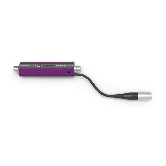
Guide to Installation and Operation 2.0 Overall View Figure 2 illustrates the SDM-272p’s major parts and their locations. The video source is connected to the 4:2:2 input BNC and the encoded signal is provided by the S-video output. Error status is provided by the status LED and mode settings are configured by two 3-position slide switches. -
Page 7: Installation
Guide to Installation and Operation 3.0 Installation 3.1 Power Supply The power supplies LKS-WSA and LKS-WSE, for 110 V and 220 V operation respectively, are used to power the SDM-272p. Each power supply provides a regulated +5 VDC@750 mA power source. The SDM-272p employs a mini XLR-3 connector for its power needs. -
Page 8: 4:2:2 Input
Guide to Installation and Operation 3.2 4:2:2 Input Connect a 4:2:2 serial digital signal to the BNC labeled 4:2:2 IN. The 4:2:2 input signal must conform to the SMPTE 259M-C standard. 3.3 S-Video Output A S-video signal conforming to the SMPTE 170M or ITU (CCIR) 624-4 standard is provided by the S-VIDEO OUTPUT connector. -
Page 9: Operation
4.0 Operation 4.1 Switch Settings Figure 5 outlines the slide switch functions. Output setup and format (SW1) Normal, Y-only, and test (SW2) Miranda Technologies inc. SDM-272p Made in Canada Figure 5: SDM-272p switch settings Output setup and format switch (SW1) 7.5 IRE:... -
Page 10: Status Led
Guide to Installation and Operation Normal, Y-only, and test pattern switch (SW2) Normal: For normal operation, set SW2 to this position. Y-Only: Setting SW2 to this position provides a monochrome output signal by forcing the output chroma to 0. Test: Set SW2 to Test in order to enable the test pattern generator. -
Page 11: Specifications
Guide to Installation and Operation 5.0 Specifications Input Signal: 4:2:2 SMPTE 259M-C (270 Mbps) Cable length: 250 m (850') Return loss: > 15 dB up to 270 MHz 75 Ω BNC Connector : Output Signal: S-video 1 Vpp nominal with sync Return loss: >...
Need help?
Do you have a question about the picoLink Series and is the answer not in the manual?
Questions and answers