Table of Contents
Advertisement
Quick Links
picoLink Series
ASD-771p
Guide to Installation
and Operation
M308-9900-101
Miranda Technologies Inc.
Specifications may be subject to change.
Technologies inc.
3499 Douglas-B.-Floreani
St-Laurent, Québec, Canada H4S 1Y6
Copyright 2002
Printed in Canada
August 2002
Miranda
Tel. 514-333-1772
Fax. 514-333-9828
www.miranda.com
AES/EBU Analog
To Digital
Converter
Advertisement
Table of Contents

Related Manuals for Miranda ASD-771p


Summary of Contents for Miranda ASD-771p
- Page 1 Series To Digital ASD-771p Converter Guide to Installation and Operation M308-9900-101 Copyright 2002 Miranda Technologies Inc. Specifications may be subject to change. Printed in Canada August 2002 Miranda Technologies inc. 3499 Douglas-B.-Floreani St-Laurent, Québec, Canada H4S 1Y6 Tel. 514-333-1772 Fax.
- Page 2 Miranda, at its sole dis- cretion. In no event shall Miranda Technologies Inc. be liable for any incidental or consequential damages, including loss of profits.
- Page 3 ASD-771p/75/110- Guide to Installation and Operation for the delivery of the loaner or exchange products or parts. Freight and insurance charges for the return of the defective product or part will also be paid by Miranda Technologies. Out-Of-Warranty Repair Policy Miranda will repair equipment which is out of Warranty.
- Page 4 ASD-771p/75/110 - Guide to Installation and Operation How to contact us: Head Office Miranda Europe Miranda Technologies Inc. 222, 226 Rue De Rosny 3499 Douglas-B.-Floreani 93100 Montreuil St. Laurent (Montreal), Que. H4S 1Y6 France Canada +1 (514) 333-1772 +33 1 55 86 87 88...
- Page 5 ASD-771p/75/110- Guide to Installation and Operation...
-
Page 6: Table Of Contents
ASD-771p/75/110 - Guide to Installation and Operation Contents page 1 ASD-771p AES/EBU Analog to Digital Converter ..1 1.1 Introduction............... 1 1.2 Features..............1 2 Overall View ..............3 3 Installation ..............5 3.1 Power Supply............5 3.2 Analog Input............. 5 3.3 AES Output............... 6 4 Operation ................ - Page 7 ASD-771p/75/110- Guide to Installation and Operation...
-
Page 8: Asd-771P Aes/Ebu Analog To Digital Converter
ASD-771p/75/110 - Guide to Installation and Operation 1 ASD-771p AES/EBU Analog to Digital Converter 1.1 Introduction The ASD-771p is the industry’s smallest 24 bit/48 kHz analog to digital audio converter. External reference input allows the out- put to be synchronized to composite video, AES-3id Digital Audio Reference (DARS) or word clock signals. - Page 9 ASD-771p/75/110- Guide to Installation and Operation...
-
Page 10: Overall View
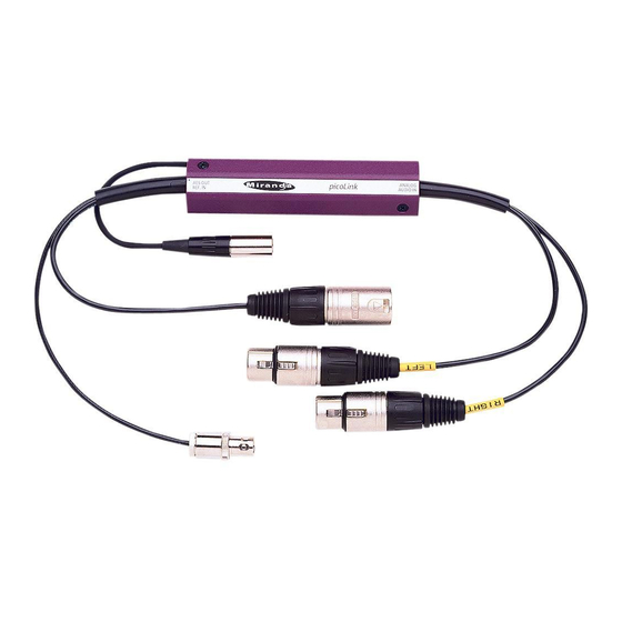
ASD-771p/75/110 - Guide to Installation and Operation 2 Overall view The figures below represents the ASD-771p/75 and the ASD- 771p/110. The analog stereo audio source is connected to the two XLR3 input connectors. A multicolor LED provides module statuses. A mini slide switch “Test”... - Page 11 ASD-771p/75/110- Guide to Installation and Operation Figure 2.2 ASD-771p, 110 Ω Version Status LED Slide switches DC power input connector Input connectors Output connector Reference input connector...
-
Page 12: Installation
3 Installation 3.1 Power Supply The power supplies LKS-WSA and LKS-WSE, for 110V and 220V operation respectively, are used to power the ASD-771p/75/110. Each power supply provides a regulated +5VDC@750mA power source. Plug the power supply into a wall or power bar outlet. The ASD- 771p uses a mini XLR-3 connector for its power needs;... -
Page 13: Aes Output
Connect a reference signal PAL, NTSC, AES-3id 75 Ω or Word clock signal to the BNC plug (female) connector. Note: The ASD-771p detects automatically a PAL, NTSC, Word clock (48 kHz) or AES-3id 75 Ω signal. When synchronization is missing, the module delivers an asynchronous AES3 (48 kHz) carri- 3.3 AES Outputs... -
Page 14: Operation
ASD-771p/75/110 - Guide to Installation and Operation 4 Operation 4.1 Switch Settings Figure 4.1 indicates the locations of the miniature switches at the back of the ASD-771p. Left Input level adjustment Figure 4.1 ASD-771p Right Input level adjustment Switches location... -
Page 15: Status Led
4.2 Status LED A multicolored LED, located beside the input, indicates the status of the module. Green: The ASD-771p is powered and has detected a valid audio signal. Yellow: Test mode is active. Red: Overload or signal absence on input. -
Page 16: Specifications
ASD-771p/75/110 - Guide to Installation and Operation 5 Specifications MEASUREMENT CONDITIONS Inputs: +24 dBu Outputs: AES FS=48 kHz ANALOG INPUT Input impedance: 15 kΩ Maximum level: +24 dBu REFERENCE INPUT 75 Ω Input impedance: AES3 OUTPUT AES3 3.4 Vp-p/110 Ω... - Page 17 ASD-771p/75/110- Guide to Installation and Operation...
-
Page 18: Schematic Diagrams
ASD-771p/75/110 - Guide to Installation and Operation 6 Schematic Diagrams...
Need help?
Do you have a question about the ASD-771p and is the answer not in the manual?
Questions and answers