Miranda picoLink Series Manual To Installation And Operation
Fiber optic to sd converter
Hide thumbs
Also See for picoLink Series:
- Manual to installation and operation (18 pages) ,
- Manual to installation and operation (11 pages) ,
- Manual to installation and operation (11 pages)
Table of Contents
Advertisement
Quick Links
Advertisement
Table of Contents

Subscribe to Our Youtube Channel
Related Manuals for Miranda picoLink Series


Summary of Contents for Miranda picoLink Series
- Page 1 FOE-171p Fiber Optic to SD Converter Guide to Installation and Operation M394-9920-102 17 Mar 2009 Miranda Technologies Inc. 3499 Douglas-B.-Floreani St-Laurent, Québec, Canada H4S 1Y6 Tel. 514-333-1772 Fax. 514-333-9828 www.miranda.com © 2009 Miranda Technologies Inc.
- Page 2 This equipment has been tested and complies with the limits in accordance with the specifications in: FCC Part 15, Subpart B CE EN50081-1:1992 CE EN50082-1:1992 Contact Miranda For technical assistance, please contact the Miranda Technical Support centre nearest you: Americas Asia Telephone: Telephone:...
-
Page 3: Table Of Contents
GUIDE TO INSTALLATION AND OPERATION Table of Contents FOE-171p Fiber Optic to HD/SD Converter....... 1 1.1 Introduction................ 1 1.2 Features ................1 Overview ................2 Installation ................3 3.1 Power Supply ..............3 3.2 Fiber Input ................. 4 3.3 4:2:2 Digital Video Output ..........4 Operation ................ - Page 4 GUIDE TO INSTALLATION AND OPERATION FOE-171p...
-
Page 5: Foe-171P Fiber Optic To Hd/Sd Converter
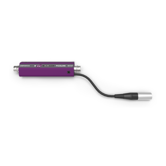
GUIDE TO INSTALLATION AND OPERATION FOE-171p Fiber Optic to HD/SD Converter Introduction The FOE-171p is a compact stand-alone optical to electrical solution for receiving digital video signals over a single mode fiber optic link. The FOE-171p has been designed to work in conjunction with the FEO-171p Electrical to Optical Transmitter. -
Page 6: Overview
GUIDE TO INSTALLATION AND OPERATION Overview Figure 2 illustrates the FOE-171p's major parts and their locations. The optical fiber input is connected using a single- mode SC connector, and the 4:2:2 digital video output appears on a BNC connector. Error status is provided by the status LED. Finally, the power source is connected to the mini-XLR type connector. -
Page 7: Installation
GUIDE TO INSTALLATION AND OPERATION Installation Power Supply The LKS-WSU power supply provides power to the FOE-171p for 110 V and 220 V operation. The power supply is a regulated +5 VDC@2.4 A power source. The FOE-171p employs a mini XLR-3 connector for its power needs. -
Page 8: Fiber Input
GUIDE TO INSTALLATION AND OPERATION Fiber Input Connect an optical signal to the SC connector labeled FIBER IN. Class 1 laser product Hazards for the Operator Active optic fibers emit radiation invisible to the naked eye. Never look directly at the end of an active optic fiber. Caution Although not considered overly dangerous for the eye, avoid accidental exposure to the optical beam... -
Page 9: Operation
GUIDE TO INSTALLATION AND OPERATION Operation There are no operating controls on the FOE-171p. Status LED The bi-colored status LED, located next to the BNC output connector, is provided to identify any input errors. The following situations are flagged: No DC power Off: Laser light detected with valid SDI signal Green:... -
Page 10: Specifications
GUIDE TO INSTALLATION AND OPERATION Specifications Optical Input Signal Compatibility: 270 Mbps SMPTE 259M-C Reclocked SMPTE 297M Sensitivity: -25 dB Fiber Type: Single Mode Connector: Optical SC/PC Electrical Output Signal: SMPTE 259M-C (270 Mbps)I Return loss: >15 dB up to 270 MHz Jitter: <0.2 UI p-p Connector:...
Need help?
Do you have a question about the picoLink Series and is the answer not in the manual?
Questions and answers