Table of Contents
Advertisement
Quick Links
Advertisement
Table of Contents

Subscribe to Our Youtube Channel
Related Manuals for Miranda SDM-872p


Summary of Contents for Miranda SDM-872p
- Page 2 - FCC Part 15, Subpart B - CE EN50081-1:1992 - CE EN50082-1:1992. How to contact us: CONTACT MIRANDA For technical assistance, please contact the Miranda Technical Support centre nearest you: Americas Asia Telephone: Telephone: +1-800-224-7882...
-
Page 3: Table Of Contents
Guide to Installation and Operation Contents page 1 SDM-872p SD/HD Serial Digital to DVI-HDTV Converter ..............1 1.1 Introduction............... 1 1.2 Features..............1 2 Overall View ..............2 3 Installation ..............3 3.1 Power Supply............3 3.2 HD/SD Serial Digital Video Input with Active Loop- through.............. -
Page 5: Sdm-872P Sd/Hd Serial Digital To Dvi-Hdtv Converter
SD and HD serial to Digital RGB for the purposes of feeding a computer monitor and projector. (CRT, LCD, Plasma, DLP, D-ILA etc). In order to support the emerging popularity of 24p equipment and digital display, the SDM-872p DVI output with selectable 3:2 sequence insertion. SD/HD... -
Page 6: Overall View
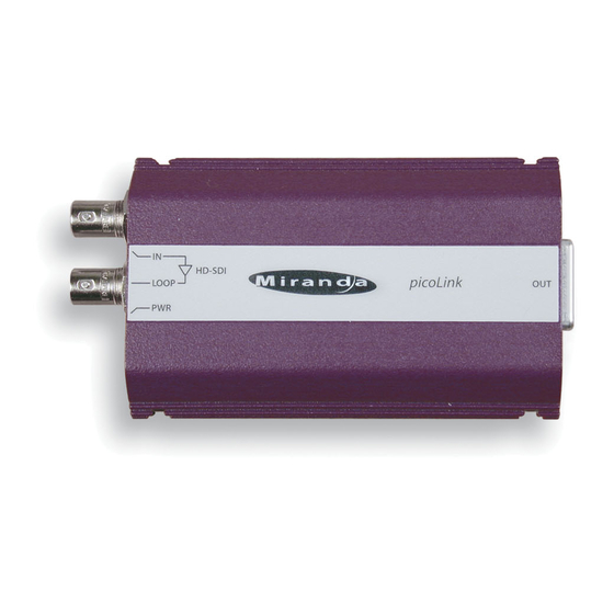
SDM-872p 2.0 Overall View Figure 2 illustrates the SDM-872p's major parts and their loca- tions. A high-definition or standard definition digital video source is connected to the HD/SD SDI IN BNC and the Digital RGB out- put is provided by the DVI-D connector. Error status is provided by the status LED. -
Page 7: Installation
Power Supply The power supplies LKS-WSU, for 110 V and 220 V operation, is used to power the SDM-872p. The power supply provides a re- gulated +5 VDC@2.4 A power source. The SDM-872p employs a mini XLR-3 connector for its power needs. Figure 3 provides a detailed pinout of the male connector. -
Page 8: Digital Rgb Video Output
SDM-872p 3.3 Digital RGB Video Output The digital RGB video output signal (DVI-HDTV) is provided by the DVI-D (female) labeled OUTPUT. The output format is auto- matically selected according to the input signal; for a complete list of the output formats and related SMPTE standards refer to... -
Page 9: Operation
Guide to Installation and Operation 4.0 Operation 4.1 Switch Settings Figure 4.1 outlines the slide switches and pushbutton selection. Figure 4.1 SDM-872p Underside DIRECT OUTPUT TEST 3:2 INSERT MARKERS 4:3 P -> PsF SDM-872p INPUT FORMAT PsF -> P Miranda Technologies Inc. - Page 10 SDM-872p Markers 4:3 Selection: Set the “Markers 4:3” slide switch to this position to display 4:3 markers on the 16:9 image. Off: The 4:3 markers are disabled. Input format Set the “Input Format” slide switch to this position for most input signal.
-
Page 11: Status Led
LOOP BNC connectors, is provided to identify any input errors and the selection of the test pattern. The following lists all possible situations. Green: Indicates that the SDM-872p is powered and has detected a valid input signal. Red: Indicates an invalid input signal or simply, there is no input signal installed. -
Page 12: Specifications
SDM-872p 5.0 Specifications Input Signal: SMPTE 292M (1.485, 1.485/1.001 Gbps) with re-clocked loop-through output Cable length: 75 m (250') (Belden 1694A) Return loss: >15 dB up to 1.5 GHz Connector: 75Ω BNC Output Signal: Digital fixed GBR (DVI) Connector: DVI-D, Female, compliant to DVI 1.0 pin out... - Page 13 Guide to Installation and Operation Supported Format nput format Standard Mode VGA & DVI Standard Delay output format SMPTE-125M Dir.Output 720x486 59.94i SMPTE-125M < 5us SMPTE-267M SMPTE-267M Dir.Output 720x576 50i < 5us 1280x720 60p SMPTE-296M Dir.Output 1280x720 60p SMPTE-296M < 5us Varicam 1:1 1280x720 24p SMPTE-296M 1 Fr.
- Page 14 SDM-872p 1920x1080 24p SMPTE-274M Dir.Output 1920x1080 24p SMPTE-274M < 5us 1920x1080 24 PsF SMPTE-274M 1 Fr. → 3:2 Insert 1920x1080 60i SMPTE-274M 1 Fr. 1920x1080 25 PsF* SMPTE-274M 1 Fr. 1920x1080 23.98p SMPTE-274M Dir. Output 1920x1080 23.98p SMPTE-274M < 5us 1920x1080 23.98 PsF SMPTE-274M 1 Fr.
Need help?
Do you have a question about the SDM-872p and is the answer not in the manual?
Questions and answers