Table of Contents
Advertisement
Quick Links
Video ADC
picoLink Series
ADC-191p
Guide to Installation
and Operation
M825-9800-100
Copyright 2007
Miranda Technologies Inc.
Specifications may be subject to change.
Printed in Canada
March 2007
Miranda
Technologies inc.
3499 Douglas-B.-Floreani
St-Laurent, Québec, Canada H4S 1Y6
Tel. 514-333-1772
Fax. 514-333-9828
www.miranda.com
Advertisement
Table of Contents

Related Manuals for Miranda ADC-191p


Summary of Contents for Miranda ADC-191p
- Page 1 Video ADC picoLink Series ADC-191p Guide to Installation and Operation M825-9800-100 Copyright 2007 Miranda Technologies Inc. Specifications may be subject to change. Printed in Canada March 2007 Miranda Technologies inc. 3499 Douglas-B.-Floreani St-Laurent, Québec, Canada H4S 1Y6 Tel. 514-333-1772 Fax. 514-333-9828...
- Page 2 FCC Part 15, Subpart B CE EN50081-1:1992 CE EN50082-1:1992. CONTACT MIRANDA For technical assistance, please contact the Miranda Technical Support centre nearest you: Americas Asia Telephone: Telephone:...
-
Page 3: Table Of Contents
Guide to Installation and Operation CONTENTS page 1.0 ADC-191p ..........1 1.1 Introduction............1 1.2 Features ............1 2.0 Physical Layout ........2 3.0 Installation ..........3 3.1 Power Supply ..........3 3.2 CAV Inputs ..........4 3.3 4:2:2 Output...........4 4.0 Operation ..........5 4.1 Switch Settings..........5... - Page 4 Guide to Installation and Operation ADC-191p...
-
Page 5: Adc-191P
Guide to Installation and Operation 1.0 ADC-191p 1.1 Introduction The ADC-191p is the industry’s smallest component analog video to 4:2:2 serial digital video ADC. This product automatically detects 525-line and 625-line CAV signals and provides a 4:2:2 serial digital output signal conforming to the SMPTE 259M-C standard. -
Page 6: Physical Layout
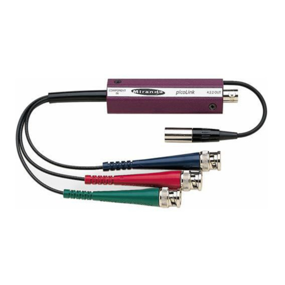
Guide to Installation and Operation 2.0 Physical Layout Figure 2 illustrates the ADC-191p’s major parts and their locations. SMPTE/EBU or Betacam sources are connected to the CAV input BNCs and the 4:2:2 serial digital output is provided by the 4:2:2 output BNC. Error status is provided by the status LED and mode settings are configured by two 3-position slide switches. -
Page 7: Installation
The power supplies LKS-WSA and LKS-WSE, for 110 V and 220 V operation respectively, are used to power the ADC-191p. Each power supply provides a regulated +5 VDC@750 mA power source. The ADC-191p employs a mini XLR-3 connector for its power needs. Figure 3 provides a detailed pinout of the male connector. -
Page 8: Cav Inputs
The CAV inputs consist of green, blue, and red color coded male BNC connectors. Male connectors are provided so as to connect the ADC-191p directly to source equipment. The supported CAV input standards are SMPTE/EBU and Betacam. The Betacam standard can be set with or without setup. -
Page 9: Operation
Guide to Installation and Operation 4.0 Operation 4.1 Switch Settings Figure 4 shows the slide switch locations and functions. Figure 4: ADC-191p switch settings Input format switch (SW1) SMPTE: For SMPTE/EBU CAV inputs, set SW1 to this position. The Y/B-Y/R-Y inputs are to be connected to the green, blue, and red connectors respectively. -
Page 10: Status Led
The bi-colored status LED is provided to identify any input errors. The following lists the possible situations. Green: Indicates the ADC-191p is powered and has detected a valid CAV input signal. Red: Indicates an error with the input signal has been detected or simply, there is no input signal installed. -
Page 11: Specifications
Mini XLR-3 Mechanical Overall size: 102 mm x 25 mm x 18 mm (4” x 1” x 0.7”) Power cable length: 127 mm (5”) Full spec. temp. range: 0° C (32° F) to 30° C (86° F) ADC-191p | 7...
Need help?
Do you have a question about the ADC-191p and is the answer not in the manual?
Questions and answers