Miranda picoLink series Manual To Installation And Operation
Sd/hd serial digital
to dvi converter
Hide thumbs
Also See for picoLink series:
- Manual to installation and operation (18 pages) ,
- Manual to installation and operation (16 pages) ,
- Manual to installation and operation (10 pages)
Table of Contents
Advertisement
Quick Links
Advertisement
Table of Contents

Subscribe to Our Youtube Channel
Related Manuals for Miranda picoLink series


Summary of Contents for Miranda picoLink series
- Page 1 SDM-874p SD/HD Serial Digital to DVI Converter Guide to Installation and Operation M804-9900-103 8 Sep 2008 Miranda Technologies Inc. 3499 Douglas-B.-Floreani St-Laurent, Québec, Canada H4S 1Y6 Tel. 514-333-1772 Fax. 514-333-9828 www.miranda.com © 2008 Miranda Technologies I...
- Page 2 This equipment has been tested and complies with the limits in accordance with the specifications in: FCC Part 15, Subpart B CE EN50081-1:1992 CE EN50082-1:1992 Contact Miranda For technical assistance, please contact the Miranda Technical Support centre nearest you: Americas Asia Telephone: Telephone:...
-
Page 3: Table Of Contents
GUIDE TO INSTALLATION AND OPERATION Table of Contents SDM-874p SD/HD Serial Digital to DVI Converter .... 1 1.1 Introduction................ 1 1.2 Features ................1 Overview ................2 Installation ................3 3.1 Power Supply ..............3 3.2 HD/SD Serial Digital Video Input & Active Loop-Through 4 3.3 RGB Output............... - Page 4 GUIDE TO INSTALLATION AND OPERATION SDM-874p...
-
Page 5: Sdm-874P Sd/Hd Serial Digital To Dvi Converter
GUIDE TO INSTALLATION AND OPERATION SDM-874p SD/HD Serial Digital to DVI Converter Introduction The SDM-874p is a miniature digital video interface, converting SDI/HDSDI video signals to Digital RGB (DVI-HDTV). It provides automatic input scan rate detection and supports a wide variety of input formats, including 525i, 625i, 720p, 1080i and 1080p. -
Page 6: Overview
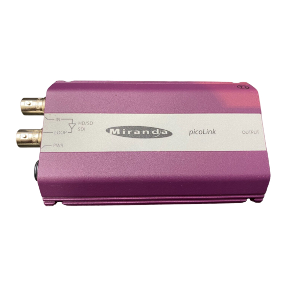
GUIDE TO INSTALLATION AND OPERATION Overview Figure 2 illustrates the SDM-874p's major parts and their locations. A high-definition or standard definition digital video source is connected to the SDI/HD SDI IN BNC and the Digital RGB output is provided by the DVI-I connector. Error status is provided by the status LED. -
Page 7: Installation
GUIDE TO INSTALLATION AND OPERATION Installation Power Supply The LKS-WSU power supply provides power to the SDM-874p for 110 V and 220 V operation. The power supply is a regulated +5 VDC@2.4 A power source. The SDM-874p employs a mini XLR-3 connector for its power needs. -
Page 8: Hd/Sd Serial Digital Video Input & Active Loop-Through
GUIDE TO INSTALLATION AND OPERATION HD/SD Serial Digital Video Input & Active Loop- Through Connect a high-definition or standard definition digital video signal to the BNC labeled SDI/HD-SDI IN: • The high-definition serial digital input signal must conform to the SMPTE 292M standard. •... -
Page 9: Operation
GUIDE TO INSTALLATION AND OPERATION Operation Figure 4 shows the control panel of the SDM-874p, indicating the five slide switches, the Select pushbutton, and the LED indicators that show the status established using the Select pushbutton. Figure 4: SDM-874p control panel Slide Switch functions: Test Enable the test pattern on the output. -
Page 10: Select Pushbutton Functions
GUIDE TO INSTALLATION AND OPERATION STD: Video levels are maintained from the SD/HD SDI input to the DVI output. EXPD: Video levels from the SD/HD SDI input (16 to 235 in 8 bits) are expanded to the full graphic range (0 to 255 in 8 bits) at the DVI output. - Page 11 GUIDE TO INSTALLATION AND OPERATION • When the pushbutton is pushed once, the LED indicating the currently selected processing mode flashes red and green. Subsequent pushes cycle the SDM-874p through the available operating modes. The available operating modes are: • Mode A: direct output –...
-
Page 12: Status Led
GUIDE TO INSTALLATION AND OPERATION See the Supported Formats table on pages 10 and 11 for a detailed list of the outputs corresponding to the supported input formats and user control settings. Status LED The multi-colored status LED, located between the input and loop-through connectors, identifies any input errors and the selection of the test pattern as follows: Green:... -
Page 13: Specifications
GUIDE TO INSTALLATION AND OPERATION Specifications INPUT Signal: SMPTE 259M-C (270Mbps) and SMPTE 292M (1.485, 1.485/1.001 Gbps) with re-clocked loop-through output Cable length: 100 m (Belden 1694A) Return loss: >15 dB up to 1.5 GHz Connector: 75W BNC OUTPUT Normal mode: DVI output compliant to EIA/CEA-861-B GFX mode DVI output compliant to VESA DMT... -
Page 14: Appendix - Supported Formats
GUIDE TO INSTALLATION AND OPERATION Appendix – Supported Formats Input format Mode Output format Switch Selected 525i 1440x486 59.94i 720x486 59.94p 1920 GFX 60p 1920x1200 60p 1280 GFX 60p 1280x768 60p 625i 1440x576 50i 720x576 50p 1920 GFX 50p 1920x1200 50p 1280 GFX 50p 1280x768 50p... - Page 15 GUIDE TO INSTALLATION AND OPERATION Supported Formats (continued) Input format Mode Output format Switch Selected 1920x1080 24PsF 1920x1080 24PsF 1920x1080 60i 1920x1080 60p 1920 GFX 60p 1920x1200 60p 1920x1080 25PsF 1920x1080 50p 1920 GFX 50p 1920x1200 50p 1920x1080 25p 1920x1080 25p 1920x1080 25PsF 1920x1080 50p 1920...
Need help?
Do you have a question about the picoLink series and is the answer not in the manual?
Questions and answers