Sign In
Upload
Manuals
Brands
ST Manuals
Controller
STEVAL-TTM007A
ST STEVAL-TTM007A Manuals
Manuals and User Guides for ST STEVAL-TTM007A. We have
1
ST STEVAL-TTM007A manual available for free PDF download: User Manual
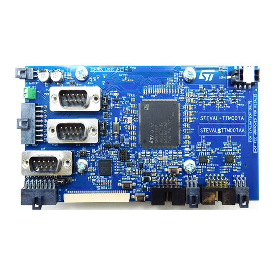
ST STEVAL-TTM007A User Manual (48 pages)
Control board for automotive applications
Brand:
ST
| Category:
Controller
| Size: 7 MB
Table of Contents
Figure 1. STEVAL-TTM007A Top View
1
Figure 2. STEVAL-TTM007A Bottom View
1
Evaluation Kit Features
2
Control Board MCU Main Features and Functional Characteristics
2
SR5E1 Features
2
Cores
2
Memories
2
Security: Hardware Security Module (HSM)
2
Safety: Comprehensive New Generation ASIL-D Safety Concept
2
Enhanced Peripherals for Fast Control Loop Capability
3
Communication Interfaces
3
Advanced Debug and Trace for High Performance Automotive Application Development
3
Others
3
Target Applications
4
Safety and Operating Instructions
5
General Terms
5
Intended Use of Evaluation Kit
5
Evaluation Kit Setup
5
Electronic Connections
5
Development Environment
6
System Requirements
6
Development Toolchains
6
Demonstration Software
6
Conventions
7
Table 1. ON/OFF Convention
7
Hardware Layout and Configuration
8
Figure 3. STEVAL-TTM007A Top View: External Connectors
8
Figure 4. STEVAL-TTM007A Bottom View: External Connectors
9
Table 2. STEVAL-TTM07A Connector Descriptions
9
Figure 5. STEVAL-TTM007A Top View: Push Button Positions
10
Table 3. Push Button Descriptions
10
Figure 6. STEVAL-TTM07A LED Positions
11
Table 4. LED Descriptions
11
Quick Start
12
Jumper Setup
12
Figure 7. STEVAL-TTM007A Jumper Positions
12
Table 5. Default Jumper Connections
12
Power Supply
13
Current Sensing Section
13
Figure 8. STEVAL-TTM007A Power Tree
13
Table 6. Configurations Available for Power Supply
13
Figure 9. Current Sensing Connector Schematic
14
Figure 10. Current Sensing RC Filtering
14
Table 7. Configurations Available for Current Sensor Supplies
14
Table 8. CON1 and CON2 Pinout
14
Resolver Circuit Section for Position Sensing
15
Figure 11. Resolver Connectors' Schematic
15
Table 9. ADC Channels: SR5E1 Pin Connection for Current Reading
15
Figure 12. Resolver Conditioning Circuit: Excitation Amplifying Stage
16
Figure 13. Resolver Conditioning Circuit: Cosine and Sine Signal Amplifying Stages
16
Table 10. RES1 and RES2 Pinout
16
Table 11. ADC and DAC Channels: SR5E1 Pin Connection for Resolver Sensing
16
Board to Board Connections
18
Figure 14. Example of Application Case Interconnections
18
Schematic Diagrams
19
Figure 15. STEVAL-TTM007A Schematic Diagram (1 of 10)
19
Figure 16. STEVAL-TTM007A Schematic Diagram (2 of 10)
20
Figure 17. STEVAL-TTM007A Schematic Diagram (3 of 10)
21
Figure 18. STEVAL-TTM007A Schematic Diagram (4 of 10)
22
Figure 19. STEVAL-TTM007A Schematic Diagram (5 of 10)
23
Figure 20. STEVAL-TTM007A Schematic Diagram (6 of 10)
24
Figure 21. STEVAL-TTM007A Schematic Diagram (7 of 10)
25
Figure 22. STEVAL-TTM007A Schematic Diagram (8 of 10)
26
Figure 23. STEVAL-TTM007A Schematic Diagram (9 of 10)
27
Figure 24. STEVAL-TTM007A Schematic Diagram (10 of 10)
28
Bill of Materials
29
Table 12. STEVAL-TTM007A Bill of Materials
29
Board Versions
42
Table 13. STEVAL-TTM007A Versions
42
Regulatory Compliance Information
43
Revision History
44
Table 14. Document Revision History
44
Advertisement
Advertisement
Related Products
ST STEVAL-ESC002V1
ST STEVAL-IHM037V1
ST STEVAL-IAS001V1
ST STEVAL-A6983NV1
ST ST10-Q
ST ST10-Q-E
ST ST10-C
ST STM8AF612x
ST STM8AF6166
ST STM8AF6199
ST Categories
Motherboard
Computer Hardware
Microcontrollers
Control Unit
Controller
More ST Manuals
Login
Sign In
OR
Sign in with Facebook
Sign in with Google
Upload manual
Upload from disk
Upload from URL