Table of Contents

Related Manuals for OLIMEX MOD-IO


Summary of Contents for OLIMEX MOD-IO
- Page 1 MOD-IO development board user's manual All boards produced by Olimex are ROHS compliant Rev. C, March 2013 Copyright(c) 2011, OLIMEX Ltd, All rights reserved Page 1 Downloaded from Elcodis.com electronic components distributor...
-
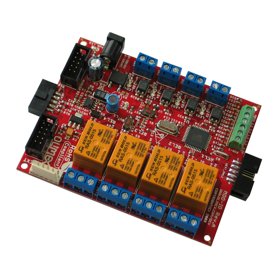
Page 2: Board Features
UEXT male/female connector. So the MCU interfaces (I2C, SPI, UART) from all chain boards are connected in parallel. Note that if you want to connect more than 1 MOD-IO board then on the interface bus (I2C or UART or SPI) has to have only one Master device. The other devices have to be Slaves. - Page 3 Four Relays – PCB: FR-4, 1.5 mm (0,062"), solder mask, silkscreen component print – Dimensions: 100x80 mm (3.94x3.15") – Page 3 Downloaded from Elcodis.com electronic components distributor...
-
Page 4: Electrostatic Warning
ELECTROSTATIC WARNING The MOD-IO board is shipped in protective anti-static packaging. The board must not be subject to high electrostatic potentials. General practice for working with static sensitive devices should be applied when working with this board. BOARD USE REQUIREMENTS... - Page 5 Programming Lock for Software Security – JTAG (IEEE std. 1149.1 Compliant) Interface – Boundary-scan Capabilities According to the JTAG Standard – Extensive On-chip Debug Support – Programming of Flash, EEPROM, Fuses, and Lock Bits through the JTAG – Interface Peripheral Features –...
- Page 6 Idle Mode: 0.35 mA – Power-down Mode: < 1 µA – Page 6 Downloaded from Elcodis.com electronic components distributor...
-
Page 7: Block Diagram
BLOCK DIAGRAM Page 7 Downloaded from Elcodis.com electronic components distributor... -
Page 8: Memory Map
MEMORY MAP Page 8 Downloaded from Elcodis.com electronic components distributor... - Page 9 Page 9 Downloaded from Elcodis.com electronic components distributor...
- Page 10 LED1 IN1-2 MISO MISO T1107A(6x3.8x2.5mm) https://www.olimex.com 100n MOSI MOSI 3.9k 1N4148/SMD OLIMEX LTD, Plovdiv, Bulgaria, 2013 BH10S IDC10S/PCB IN1-1 H11A817SMD This schematic is released under the Creative Commons Attribution-Share Alike 3.0 United States License. Downloaded from Elcodis.com electronic components distributor...
-
Page 11: Board Layout
Crystal Quartz 32.768kHz connected to Atmega16L pin 25 ((TOSC1)PC6) and pin 26 ((TOSC2)PC7). RESET CIRCUIT MOD-IO reset circuit includes Reset scheme MCP130T (U2), AVRISP connector pin 5, JTAG connector pin 6, Atmega16L pin 4 (RESET), R9 (100Ohm), R10 (10k), C10 (100nF) and RST button. - Page 12 CONNECTOR DESCRIPTIONS AVRISP Pin # Signal Name MOSI 3.3V MISO JTAG Pin # Signal Name 3.3V 3.3V Pin # Signal Name 3.3V Page 12 Downloaded from Elcodis.com electronic components distributor...
- Page 13 UEXT_MALE More info available here: https://www.olimex.com/Products/Modules/UEXT/ Pin # Signal Name MISO MOSI UEXT_FEMALE Pin # Signal Name MISO MOSI Page 13 Downloaded from Elcodis.com electronic components distributor...
- Page 14 IN1, IN2 IN3, IN4 Please note that the opto-isolated inputs IN1, IN2, IN3, IN4 in earlier revisions were able to receive signals in the 3V to 6V range. R27, R29, R31, R33 were 330R and R28, R30, R32, R34 were R4.7k. We have now adjusted the values of the resistors in that part of the schematic in latest revisions to allow higher voltage input in the 3.3V-24.0V range.
- Page 15 AIN-2 Please note that the analog inputs by default are as big as the input levels but you might change this. Just calculate (and mount/replace) the needed resistors R23/R24 and R25/R26. Pin # Signal Name Connected to (ADC5)PA5 (ADC4)PA4 AGND Analog GND PWR_J Pin #...
-
Page 16: Jumper Description
JUMPER DESCRIPTION There are no jumpers on this board. INPUT/OUTPUT User button with name BUT – connected to Atmega16L pin 11 ((INT0)PD2). Reset button with name RST – connected to Atmega16L pin 4 (RESET). Status LED (yellow) with name STAT – connected via R11 (330 Ohm) to Atmega16l pin 43 ((AIN1)PB3). -
Page 17: Mechanical Dimensions
MECHANICAL DIMENSIONS Page 17 Downloaded from Elcodis.com electronic components distributor... -
Page 18: Available Demo Software
AVAILABLE DEMO SOFTWARE There are two firmware available for MOD-IO: one is for RS232 control and the other is for I2C control. They might be found at the web page of MOD-IO. Direct download links: MOD-IO I2C (newer) firmware C source and hex –... -
Page 19: Order Code
ORDER CODE MOD-IO assembled and tested. How to order? You can order directly from our web shop or from any of our distributors. The list of distributors might be found here: https://www.olimex.com/Distributors. Check our web https://www.olimex.com for more info. Revision history: Board's revision: Rev. - Page 20 This document is intended only to assist the reader in the use of the product. OLIMEX Ltd. shall not be liable for any loss or damage arising from the use of any information in this document or any error or omission in such information or any incorrect use of the product.
- Page 21 For product support, hardware information and error reports mail to: support@olimex.com. Note that we are primarily a hardware company and our software support is limited. Please consider reading the paragraph below about the warranty of Olimex products. Warranty and returns: Our boards have lifetime warranty against manufacturing defects and components.
Need help?
Do you have a question about the MOD-IO and is the answer not in the manual?
Questions and answers