
Related Manuals for OLIMEX MOD-MP3-X


Summary of Contents for OLIMEX MOD-MP3-X
- Page 1 MOD-MP3-X and MOD-MP3-X-BAT development boards Users Manual All boards produced by Olimex are ROHS compliant Revision D, March 2012 Copyright(c) 2011, OLIMEX Ltd, All rights reserved Page 1...
-
Page 2: Board Features
USB must not be plugged in and the board has to be power supplied via external power supply (PWR_JACK or BATTERY). MOD-MP3-X ships in two variants – with and without battery. The battery variant employs a Li-ion 3.7 V, 1200 mAh rechargeable battery and an on-board bat- tery charger. -
Page 3: Electrostatic Warning
Dimensions: 60 x 60 mm ( 2.36 x 2.36") ELECTROSTATIC WARNING: The MOD-MP3-X board is shipped in protective anti-static packaging. The board must not be subject to high electrostatic potentials. General practice for working with static sensitive devices should be applied when working with this board. - Page 4 − Internal 32 kHz RC − PLL for CPU clock − Dedicated 32 kHz oscillator for RTC with calibration − Low power − Sleep, Stop and Standby modes − VBAT supply for RTC and backup registers − 2 x 12-bit, 1 μs A/D converters (16-channel) −...
-
Page 5: Block Diagram
BLOCK DIAGRAM: Page 5... -
Page 6: Memory Map
MEMORY MAP: Page 6... - Page 7 AUDIO CODEC FEATURES: − Decodes Ogg Vorbis; MPEG 1 & 2 audio layer III (CBR +VBR +ABR); layers I & II optional; MPEG4 / 2 AAC-LC(+PNS), HE-AAC v2 (Level 3) (SBR + PS); WMA4.0/4.1/7/8/9 all profiles (5-384 kbps); WAV (PCM + IMA ADPCM); General MIDI 1 / SP-MIDI format 0 files −...
-
Page 8: Audio Codec Block Diagram
AUDIO CODEC BLOCK DIAGRAM: Page 8... - Page 9 SCHEMATIC: WAKE-UP 47uF/6.3V/TANT 1N4148 100nF 100nF DGND4 DGND3 100nF DGND2 DGND1 DGND0 AGND3 10uF/10V AGND2 IOVDD2 AGND1 IOVDD1 AGND0 IOVDD0 CVDD3 AVDD2 CVDD2 AVDD1 CVDD1 AVDD0 CVDD0 100nF 100nF 100nF 100nF 100nF 100nF 100nF 10uF/10V 680K 47 k Page 9...
-
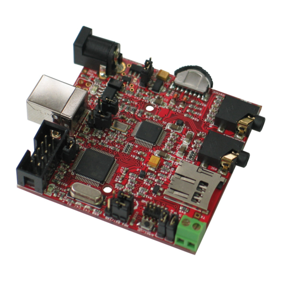
Page 10: Board Layout
BOARD LAYOUT: Page 10... -
Page 11: Power Supply Circuit
The programmed board power consumption is about 70 mA with all peripherals enabled. RESET CIRCUIT: MOD-MP3-X reset circuit for VS1053 includes RC group - R7 (100kΩ) pull- up and C12 (100nF), jumper MP3_RST, jumper VLS_RST, STM32F103RBT6 pin 43 (PA10/USART1_RX/TIM1_CH3) and VS1053 pin 3 (XRESET). -
Page 12: Clock Circuit
CLOCK CIRCUIT: Quartz crystal Q1 (12.288 MHz) is connected to VS1053 pin 17 (XTALO) and pin 18 (XTALI). Quartz crystal Q2 (8 MHz) is connected to STM32F103RBT6 pin 5 (PD0/OSC_IN) and pin 6 (PD1/OSC_OUT). JUMPER DESCRIPTION: UEXT/BAT When this jumper is shorted in position UEXT – the board is power suppied via UEXT. - Page 13 In this mode you can use RXD and TXD signals of UEXT connector to communicate between MOD-MP3-X and your computer. For this purpose, for example, you can use our module MOD-USB-RS232, which creates a virtual COM Port. The COM Port setting are 9600bps 8N1.
- Page 14 3 (PC14/OSC32_IN). Battery level status LED (STAT2) activity: - When powered by the battery the MOD-MP3-X indicated low battery level. If voltage of the battery falls below 3.3V then the STAT2 LED starts to blink. - If an external power source is connected, then battery starts charging. In this case STAT2 LED is constantly lit while battery is charging and turns off when battery is fully charged.
-
Page 15: External Connectors Description
Important note: If you apply power to a host device and then connect the host to the UEXT of MOD- MP3-X it might restart your host. The workaround is to connect the host to the UEXT of MOD-MP3-X and then apply power to the host! - Page 16 SWD: Pin # Signal Name VCC (3.3V) TMS/SWD TCK/SWCLK CUT (NC) USB: Pin # Signal Name USB_DETECT USBDM USBDP Page 16...
- Page 17 MIC: Pin # Signal Name MICN MICP/LINE1 MICP/LINE1 HEADPHONE: Pin # Signal Name GBUF RIGHT LEFT SD/MMC: Pin # Signal Name MCIDAT2 SPI2_NSS SPI2_MOSI SPI2_SCK SPI2_MISO MCIDAT1 Not Connected Not Connected Not Connected Not Connected Page 17...
- Page 18 EEPGM: Pin # Signal Name SPI2_MISO SPI2_MOSI SPI2_NSS Via BOOT_E to SW-CS1 Page 18...
-
Page 19: Mechanical Dimensions
MECHANICAL DIMENSIONS: Page 19... -
Page 20: Available Demo Software
AVAILABLE DEMO SOFTWARE: MOD-MP3-X-Demo Page 20... -
Page 21: Order Code
ORDER CODE: MOD-MP3-X - assembled and tested board How to order? You can order to us directly or by any of our distributors. Check our web www.olimex.com/dev for more info. Revision history: Manual's revision: Rev. C, July 2011 In “Introduction” added information about working as mass storage device and note for UEXT smart control mode. - Page 22 This document is intended only to assist the reader in the use of the product. OLIMEX Ltd. shall not be liable for any loss or damage arising from the use of any information in this document or any error or omission in such information or any incorrect use of the product.
- Page 23 Mouser Electronics Authorized Distributor Click to View Pricing, Inventory, Delivery & Lifecycle Information: Olimex Ltd. MOD-MP3-X-BAT MOD-MP3-X...
Need help?
Do you have a question about the MOD-MP3-X and is the answer not in the manual?
Questions and answers