
Related Manuals for OLIMEX MOD-IO


Summary of Contents for OLIMEX MOD-IO
- Page 1 MOD-IO Open-source hardware UEXT extension board with relays and USER’S MANUAL Document revision C, May 2020 Designed by OLIMEX Ltd, 2014 All boards produced by Olimex LTD are ROHS compliant...
-
Page 2: Disclaimer
This document is intended only to assist the reader in the use of the product. OLIMEX Ltd. shall not be liable for any loss or damage arising from the use of any information in this document or any error or omission in such information or any incorrect use of the product. -
Page 3: Table Of Contents
1.3 Board variants ........................... 6 1.4 Board version used in the manual ....................6 1.5 Document organization ........................6 CHAPTER 2: SETTING UP THE MOD-IO BOARD ............. 7 2. Introduction to the chapter ........................ 7 2.1 Electrostatic and electrical polarity warning .................. 7 2.2 Hardware requirements ........................ - Page 4 OLIMEX© 2020 MOD-IO user's manual 5.9 Additional hardware components ....................24 CHAPTER 6: SCHEMATICS ..................25 6. Introduction to the chapter ......................25 6.1 Eagle schematic ..........................25 6.2 Physical dimensions ......................... 27 CHAPTER 7: REVISION HISTORY AND SUPPORT ..........28 7.
-
Page 5: Chapter 1: Overview
Thank you for choosing the MOD-IO extension module from Olimex! This document provides a user’s guide for the MOD-IO board. As an overview, this chapter gives the scope of this document and lists the board’s features. The document’s organization is then detailed. -
Page 6: Board Variants
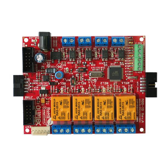
OLIMEX© 2020 MOD-IO user's manual MOD-IO provides 4 relays with proper connector that allow the switching of circuits. The board is also equipped with 4 optocouplers (also known as opto-isolators) that transfer electrical signals between two isolated circuits by using light. MOD-IO also has 4 analog inputs won a connector. -
Page 7: Chapter 2: Setting Up The Mod-Io Board
In rare cases different polarity might cause hardware damage to one of the boards in your setup. 2.2 Hardware requirements In order to set up the MOD-IO optimally one or more additional items may be used. They might be generally placed in three categories: Required –... -
Page 8: Software Requirements
SY0612E-CHINA – cheaper power supply adapter 50Hz (for EU) 12V/0.5A for A10-OLinuXino-LIME 2.3 Software requirements Olimex provides the sources of the firmware built-in MOD-IO. The project was created and compiled with AVR studio 4 In order to edit the firmware you would need to set up an AVR environment. -
Page 9: Changing The Firmware
You can connect more than two boards this way. Note that if you want to use more than one MOD-IO on the same I2C bus you would need to change the built-in the firmware identifier. Each board needs a unique address. There is a command to change discussed in the next chapter –... -
Page 10: Default Firmware Description
OLIMEX© 2020 MOD-IO user's manual 2.7 Default firmware description The demo is built-in each MOD-IO board. The source code might be found in the software section at the product page at our web site. Direct link to the board's web-page: https://www.olimex.com/Products/Modules/IO/MOD-IO/resources/MOD-IO.pdf Direct link to the latest firmware: https://www.olimex.com/Products/Modules/IO/MOD-IO/resources/MOD-IO(I2C-Slave)_v1.02.zip... -
Page 11: Getting The State Of Opto-Isolators
R – read mode, should be 1 dddd – bitmap of the input states received from the MOD-IO board, i.e. bit0 corresponds to IN1, bit1 to IN2 and so on. '1' means that power is applied to the optocoupler, '0' means the opposite. -
Page 12: Reading The Value Of An Analog Input
OLIMEX© 2020 MOD-IO user's manual 2.7.3 Reading the value of an analog input Get the voltage applied to one of the analogue inputs of the board. The board features four 10bit resolution analogue inputs (input voltages from 0 – 3.3V) and each of them is read with a separate command. -
Page 13: Changing The I2C Address Of A Board
OLIMEX© 2020 MOD-IO user's manual /* To convert digital reading to voltage use this */ voltage = (analog*3.3)/1023; 2.7.4 Changing the I2C address of a board Sets new slave address to the board. The board ships with default 7bit address 0×58 that can be changed to any other 7bit value in order for the host to interface more than 1 device connected on the bus at the same time. -
Page 14: Arduino With Mod-Io
We provide a ready-to-use library for Arduino IDE with an example code for turns on and off all relays of MOD-IO. The code also allows the reading and printing of all digital inputs and all analog inputs over the serial monitor. In order to set it up first download the archive from the link below: https://www.olimex.com/Products/Modules/IO/MOD-IO/resources/MOD-IO-ARDUINO.zip... - Page 15 OLIMEX© 2020 MOD-IO user's manual To read digital inputs: # i2cget -y -f 2 0x58 0x20 c To read analog value of IN1: # i2cset -y -f 2 0x58 0x30 # i2cget -y -f 2 0x58 w To change address to 0×22:...
-
Page 16: Chapter 3: Mod-Io Board Description
Here you get acquainted with the main parts of the board. Note the names used on the board might differ from the names used below to describe them. For the actual names check the MOD-IO board itself. 3.1 Layout (top view) -
Page 17: Chapter 4: The Atmega16A Microcontroller
In this chapter is located the information about the heart of OLinuXino – its microcontroller. The information is a modified version of the datasheet provided by its manufacturers. 4.1 The processor MOD-IO uses an 8-bit AVR microcontroller with 16K Bytes In-System Programmable Flash, with these features: High-performance, Low-power AVR® 8-bit Microcontroller ... - Page 18 OLIMEX© 2020 MOD-IO user's manual Internal Calibrated RC Oscillator External and Internal Interrupt Sources Six Sleep Modes: Idle, ADC Noise Reduction, Power-save, Power-down, Standby and Extended Standby I/O and Packages 32 Programmable I/O Lines Operating Voltages ...
-
Page 19: Chapter 5: Connectors And Pinout
Notes regarding the interfaces are given. 5.1 Communication with MOD-IO There are several ways for communication with MOD-IO and its main microcontroller ATMEGA16A. The three typical communication routines are: via I2C by utilizing the default firmware; via ISP with a compatible programmer tool and writing own code;... -
Page 20: Avrisp Connector
10-pin connector) to it. Make sure your programmer supports the programming of ATMEGA16A microcontroller. Almost any ISP programmer would be capable of programming the chip. OLIMEX sells at least two programmers suitable for the board – they are named AVR-ISP500 and AVR-ISP-MK2 – both working fine with all versions of Atmel Studio and also open source tools like AVRDude. -
Page 21: Ext
OLIMEX© 2020 MOD-IO user's manual 5.4 EXT The EXT connector has 4 pins from the ATMEGA16A's port D – PD4, PD5, PD6 and PD7; it has a VCC and GND for easier access also. Pin # Signal Name 3.3V Page 21 of 30... -
Page 22: Uext_Male
MOSI 5.6 UEXT_FEMALE The UEXT female connector is not typical for the OLIMEX boards. It allows multiple MOD-IO boards to be connected to each other even without the need of a cable! Just plug the UEXT_FEMALE of board 1 to the UEXT_MALE of board 2. -
Page 23: In1, In2 In3, In4 - Digital Inputs With Opto-Isolators
OLIMEX© 2020 MOD-IO user's manual 5.7.1 IN1, IN2 IN3, IN4 – digital inputs with opto-isolators Pin # Signal IN1 connected to (T0)PB0 – signal I4 IN2 connected to (T1)PB1 – signal I3 IN3 connected to (AIN0/INT2)PB2 – signal I2 IN4 connected to (INT1)PD3 – signal I1 The digital inputs high position would typically mean input signal is in the (3-24)V range. -
Page 24: Pwr Jack
MOD-IO user's manual 5.8 PWR jack The power jack used is the typical 2.5mm one used by Olimex in most of our products. You should provide 6V-20V AC or 8V-30V DC. The required current depends on the peripherals connected to the board. -
Page 25: Chapter 6: Schematics
MOD-IO user's manual CHAPTER 6: SCHEMATICS 6. Introduction to the chapter In this chapter is located information about the schematics describing logically and physically MOD-IO. 6.1 Eagle schematic Latest MOD-IO schematics may be found at its web-page in the “HARDWARE” section: https://www.olimex.com/Products/Modules/IO/MOD-IO/... - Page 26 OLIMEX© 2020 MOD-IO user's manual DB104(SMD) PWR_J VR1(5V) green 1uF/50v 220uF/35V 3.3V VR2(3.3V) EN 5 LM1117IMPX-ADJ OUT4-3 SW 1 REL4 REL4 YDJ-1134 RAS-05-15 100uH/SW68 8-30 VDC 1N4148/SMD RT 6 ADJ/GND N.C. PWR_LED OUT4-2 GND 7 3.3V 150k 1N5819(smd) 240R/1% OUT4-1 8.2K...
-
Page 27: Physical Dimensions
OLIMEX© 2020 MOD-IO user's manual 6.2 Physical dimensions Note that all dimensions are in mm. Page 27 of 30... -
Page 28: Chapter 7: Revision History And Support
OLIMEX© 2020 MOD-IO user's manual CHAPTER 7: REVISION HISTORY AND SUPPORT 7. Introduction to the chapter In this chapter you will find the current and the previous version of the document you are reading. Also the web-page for your device is listed. Be sure to check it after a purchase for the latest available updates and examples. -
Page 29: Useful Web Links And Purchase Codes
How to purchase? You can purchase directly from our online shop or from any of our distributors. Note that usually it is faster and cheaper to purchase Olimex products from our distributors. List of confirmed Olimex LTD distributors and resellers: https://www.olimex.com/Distributors. -
Page 30: Product Support
All goods are checked before they are sent out. In the unlikely event that goods are faulty, they must be returned, to OLIMEX at the address listed on your order invoice. OLIMEX will not accept goods that have clearly been used more than the amount needed to evaluate their functionality.
Need help?
Do you have a question about the MOD-IO and is the answer not in the manual?
Questions and answers