
Related Manuals for OLIMEX MSP430-CCRF


Summary of Contents for OLIMEX MSP430-CCRF
- Page 1 MSP430-CCRF development board User's manual All boards produced by Olimex are ROHS compliant Revision C, July 2013 OLIMEX Ltd, All rights reserved Page 1...
-
Page 2: Board Features
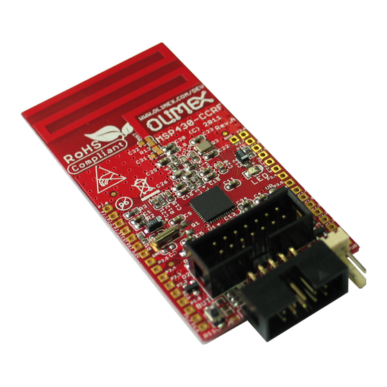
Texas Instruments. This ultra-low-power microcontroller has integrated CC1101 RF transceiver. The board has also UEXT, which can be modified as device or host. MSP430-CCRF can communicate with other boards with integrated CC1101 RF transceiver via radio connection. BOARD FEATURES: Microcontroller: CC430F5137IRGZ ... -
Page 3: Electrostatic Warning
ELECTROSTATIC WARNING: The MSP430-CCRF board is shipped in protective anti-static packaging. The board must not be subject to high electrostatic potentials. General practice for working with static sensitive devices should be applied when working with this board. BOARD USE REQUIREMENTS: Cables: The cable you will need depends on the programmer/debugger you would use. - Page 4 12-Bit A/D Converter With Internal Reference, Sample-and-Hold, and Autoscan Features Comparator 128-bit AES Security Encryption/Decryption Coprocessor 32-Bit Hardware Multiplier Three-Channel Internal DMA Serial On-board Programming, No External Programming Voltage Needed Embedded Emulation Module (EEM) ...
- Page 5 5, 3 - represents two instantiations of Timer_A, the first instantiation having 5 and the second instantiation having 3 capture compare registers and PWM output generators, respectively. Page 5...
- Page 6 BLOCK DIAGRAM:...
-
Page 7: Memory Organization
MEMORY ORGANIZATION: (1) All memory regions not specified here are vacant memory, and any access to them causes a Vacant Memory Interrupt Page 7... - Page 8 SCHEMATIC:...
-
Page 9: Board Layout
The programmed board power consumption is about 25 mA with all peripherals enabled. RESET CIRCUIT: MSP430-CCRF reset circuit includes R2 (330Ω), R1 (33k), C1 (2.2nF), JTAG pin 11 and CC430F5137IRGZ pin 40 (#RST/SWBTDIO). CLOCK CIRCUIT: Quartz crystal Q1 32.768 kHz is connected to CC430F5137IRGZ pin 44 (P5.0/XIN) and pin 43 (P5.1/XOUT). -
Page 10: Jumper Description
JUMPER DESCRIPTION: This jumper, when is in position 1-2 – UEXT pin 3 (signal TX) is connected to CC430F5137IRGZ pin 5 (signal BSLTX/UCA0TXD); when the jumper is in position 2-3- UEXT pin 3 (signal TX) is connected to CC430F5137IRGZ pin 6 (signal BSLRX/UCA0RXD) Default state is shorted in position 2-3. -
Page 11: External Connectors Description
EXTERNAL CONNECTORS DESCRIPTION: JTAG: Pin # Signal Name Pin # Signal Name JTAG power supply Not Connected TEST/SWBTCK Not Connected #RST/SWBTDIO BSLTX/UCA0TXD Not Connected BSLRX/UCA0RXD PWR: Pin # Signal Name Page 11... - Page 12 UEXT: Pin # Signal Name UCB0_MISO/SCL UCB0_MOSI/SDA UCB0_CLK UCB0_STE Page 12...
- Page 13 Pin holes: Pin # Signal Name Pin # Signal Name PJ.0 P2.6 P2.6 PJ.1 P2.7 P2.7 PJ.2 P3.0 P3.0 PJ.3 P3.1 P3.1 TEST TEST/SWBTCK P3.2 P3.2 #RST/SWBTDIO P3.3 P3.3 3.3V P3.4 P3.4 P3.5 P3.5 P2.5 P2.5 P3.6 P3.6 P2.4 P2.4 P3.7 P3.7 P2.3...
-
Page 14: Mechanical Dimensions
MECHANICAL DIMENSIONS: Page 14... -
Page 15: Available Demo Software
There is a number of example for MSP430-CCRF compatible with IAR Embedded Workbench for MSP430 v4.21. Unfortunately, it is possible that the code would not compile under IAR for MSP430 v5.xx due to incompatibility between versions. The code is available at the MSP430-CCRF web page at OLIMEX LTD web site. -
Page 16: Order Code
Rev. A, June 2011 - in BOARD FEATURES - added Supported radio frequencies bands, Maximal permissible distance between two MSP430-CCRF boards, RTC crystal and “Not typical power jack” changed to “PWR jack for 2 x 1.5V AA batteries“ Rev. B, November 2011 - BOARD FEATURES –... - Page 17 received” is changed to “RF Connection_ press BUT”. “RF Connection_toggle LED” was added. Rev. C, November 2013 - SCHEMATIC – revision B of the schematic added - updated supported debuggers list - improved the spelling of the document - added more info about revisions - expanded warranty and support page Page 17...
- Page 18 All goods are checked before they are sent out. In the unlikely event that goods are faulty, they must be returned, to OLIMEX at the address listed on your order invoice. OLIMEX will not accept goods that have clearly been used more than the amount needed to evaluate their functionality.
- Page 19 Mouser Electronics Authorized Distributor Click to View Pricing, Inventory, Delivery & Lifecycle Information: Olimex Ltd. MSP430-CCRF...
Need help?
Do you have a question about the MSP430-CCRF and is the answer not in the manual?
Questions and answers