
Related Manuals for OLIMEX MSP430-T5510


Summary of Contents for OLIMEX MSP430-T5510
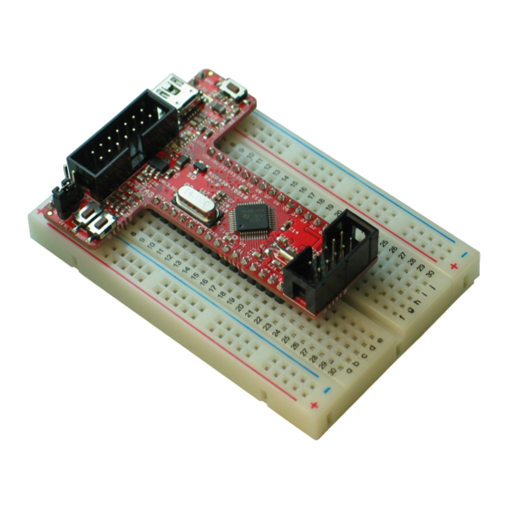
- Page 1 MSP430-T5510 development board for breadboarding USER’S MANUAL Revision A, August 2012 Designed by OLIMEX Ltd, 2012 All boards produced by Olimex LTD are ROHS compliant...
- Page 2 This document is intended only to assist the reader in the use of the product. OLIMEX Ltd. shall not be liable for any loss or damage arising from the use of any information in this document or any error or omission in such information or any incorrect use of the product.
-
Page 3: Table Of Contents
1.1 Features ..........................5 1.2 Target market and purpose of the board ................5 1.3 Organization .......................... 6 CHAPTER 2: SETTING UP THE MSP430-T5510 BOARD ........7 2. Introduction to the chapter ....................7 2.1 Electrostatic warning ......................7 2.3 Hardware requirements ....................... 7 2.5 Powering the board and operating modes ................ - Page 4 OLIMEX© 2012 MSP430-T5510 User's Manual 6.6.7 HW_SCL/SW_SCL and HW_SDA/SW_SDA ............20 6.7 Additional hardware components ..................20 CHAPTER 7: BLOCK DIAGRAM AND MEMORY ........... 21 7. Introduction to the chapter ....................21 7.2 Processor block diagram ....................21 7.3 Physical memory map ......................22 CHAPTER 8: SCHEMATICS ..................
-
Page 5: Chapter 1: Overview
Thank you for choosing the MSP430-T5510 development board from Olimex! This document provides a user’s guide for the Olimex MSP430-T5510 board. As an overview, this chapter gives the scope of this document and lists the board’s features. The document’s organization is then detailed. -
Page 6: Organization
– Chapter 2 provides a guide for quickly setting up the board and software notes – Chapter 3 contains the general board diagram and layout – Chapter 4 describes the component that is the heart of the board: the MSP430-T5510 microcontroller –... -
Page 7: Chapter 2: Setting Up The Msp430-T5510 Board
CHAPTER 2: SETTING UP THE MSP430-T5510 BOARD 2. Introduction to the chapter This section helps you set up the MSP430-T5510 development board for the first time. Please consider first the electrostatic warning to avoid damaging the board, then discover the hardware and software required to operate the board. -
Page 8: Powering The Board And Operating Modes
Additional components and extension boards (not required for basic operation!): - UEXT expansion boards All OLIMEX boards which names start with MOD, are compatible with the UEXT interface. There are over 20 different functionalities you can add via the UEXT. Notice that there is multiplexing between the Arduino platform connector (for the shields) and the UEXT. -
Page 9: Easymsp And Energia
BOOT button and press RESET button, then release BOOT. 2.7 EasyMSP and Energia MSP430-T5510 is intended to work with Energia - an Arduino-like IDE for MSP430. The community is working on adding full support for Energia. At the time of writing this manual such support isn't fully added but it is on the way. -
Page 10: Chapter 3: Msp430-T5510 Board Description
3. Introduction to the chapter Here you get acquainted with the main parts of the board. Note the names used on the board might differ from the names used below to describe them. For the actual names check the MSP430-T5510 board itself. -
Page 11: Layout (Bottom View)
OLIMEX© 2012 MSP430-T5510 User's Manual 3.2 Layout (bottom view) Page 11 of 27... -
Page 12: Chapter 4: The Msp430F5510 Microcontroller
MSP430-T5510 User's Manual CHAPTER 4: THE MSP430F5510 MICROCONTROLLER 4. Introduction to the chapter In this chapter is located the information about the heart of MSP430-T5510 – its microcontroller MSP430F5510. The information is a modified version of the datasheet provided by its manufacturers. - Page 13 OLIMEX© 2012 MSP430-T5510 User's Manual 16-Bit Timer TA1, Timer_A With Three Capture/Compare Registers 16-Bit Timer TA2, Timer_A With Three Capture/Compare Registers 16-Bit Timer TB0, Timer_B With Seven Capture/Compare Shadow Registers Two Universal Serial Communication Interfaces - USCI_A0 and USCI_A1 Each Supporting:...
-
Page 14: Chapter 5: Control Circuity
Q2 - 4 MHz quartz crystal is connected to pins 45 and 46 of the MSP430F5510 processor. 5.3 Power supply circuit The power supply circuit of MSP430-T5510 allows powering via different sources – from the miniUSB (the device will draw it's required current automatically, however ensure the USB port is standard compatible and can provide at least 1A of current), from the JTAG or via the “Vin”... -
Page 15: Chapter 6: Connectors And Pinout
*The information lines can be switched via the SMD jumpers TI_RST/OLI_RST and TI_TST/OLI_TST. This might be required for different programmers. If you use Texas Instruments programmer switch them to TI_RST and TI_STS. If using Olimex programmer switch to OLI_RST and OLI_TST. By default they are in Olimex position. -
Page 16: Uext Connector
OLIMEX© 2012 MSP430-T5510 User's Manual 6.2 UEXT connector MSP430-T5510 board has a UEXT connector and can interface Olimex's UEXT expansion modules. For more information on UEXT please visit: http://www.olimex.com/dev/OTHER/UEXT.pdf UEXT connector Pin # Signal Name 3.3V D1(TXD) D0(RXD) SW_SCL/NC* SW_SDA/NC*... -
Page 17: Jumper Description
OLIMEX© 2012 MSP430-T5510 User's Manual 6.4 MINI USB Note that this is not USB OTG (On-The-Go). Pin # Signal Name Not connected 6.5 Jumper description Please note that the jumpers on the board are ONLY SMD type. For setting the SMD jumpers please consider that if you feel insecure of your soldering/cutting technique it is better not to try to adjust those jumpers. -
Page 18: Chg_D
The default position is set for software SPI – SW_SCL closed + SW_SDA closed. 6.7 Additional hardware components The components below are mounted on MSP430-T5510 but are not discussed above. They are listed here for completeness: Reset button - used for hardware reset of the board BUT –... - Page 19 OLIMEX© 2012 MSP430-T5510 User's Manual BOOT button – used for starting the MSP430 bootstrap loader LED1 (Green) + Power LED2 (Red) Page 19 of 27...
-
Page 20: Chapter 7: Block Diagram And Memory
OLIMEX© 2012 MSP430-T5510 User's Manual CHAPTER 7: BLOCK DIAGRAM AND MEMORY 7. Introduction to the chapter On the next page you can find a memory map for this family of processors. It is strongly recommended to refer to the original datasheet released by NXP for one of higher quality. -
Page 21: Physical Memory Map
OLIMEX© 2012 MSP430-T5510 User's Manual 7.3 Physical memory map This is the memory map diagram from the original datasheet of MSP430F5510. Page 21 of 27... -
Page 22: Chapter 8: Schematics
United States License. 8.1 Eagle schematic MSP430-T5510 schematic is visible for reference here. You can also find them on the web page for MSP430-T5510 at our site: https://www.olimex.com/dev/msp430-t5510.html. They are located in HARDWARE section. The EAGLE schematic is situated on the next page for quicker reference. - Page 23 OLIMEX© 2012 MSP430-T5510 User's Manual JTAG P_IN TI_RS T/OLI_RST HN1x2(default:close) defa ult state:2-3 close 3.3V 3.3V AVCC AVCC P_OUT JTAG HN1x2(default:open) #RST DVCC1 P1_7/TA1_0 DVCC2 P1_6/TA1CLK/CBOUT P1_5/TA0_4 DVSS1 P1_4/TA0_3 DVSS2 P1_3/TA0_2 470nF P1_2/TA0_1 VCORE P1_1/TA0_0 BH14S P1_0/TA0CLK/ACLK 220nF TEST AVCC1...
-
Page 24: Physical Dimensions
OLIMEX© 2012 MSP430-T5510 User's Manual 8.2 Physical dimensions Note that all dimensions are in mils. The highest elements on the board are the two connectors – UEXT and JTAG – 320mil each (without the PCB). Page 24 of 27... -
Page 25: Chapter 9: Revision History And Support
OLIMEX© 2012 MSP430-T5510 User's Manual CHAPTER 9: REVISION HISTORY AND SUPPORT 9. Introduction to the chapter In this chapter you will find the current and the previous version of the document you are reading. Also the web-page for your device is listed. Be sure to check it after a purchase for the latest available updates and examples. -
Page 26: Useful Web Links And Purchase Codes
MSP430-JTAG-TINY – tiny in size but powerful JTAG programmer https://www.olimex.com/dev/msp-jtag-tiny.html USB-MINI-CABLE – USB mini to USB-A cable The latest price list can be found at http://olimex.com/dev/pricelist.html. How to order? You can order to us directly or by any of our distributors. -
Page 27: Product Support
MSP430-T5510 User's Manual 9.3 Product support For product support, hardware information and error reports mail to: support@olimex.com. Note that we are primarily a hardware company and our software support is limited. Please consider reading the paragraph below about the warranty of Olimex products. - Page 28 Mouser Electronics Authorized Distributor Click to View Pricing, Inventory, Delivery & Lifecycle Information: Olimex Ltd. MSP430-T5510...
Need help?
Do you have a question about the MSP430-T5510 and is the answer not in the manual?
Questions and answers