Advertisement
Quick Links
Assembly Instructions
Assembly Instructions
Important
Before you begin, read and comply with all safety and operating instructions,
and ensure all parts and correct quantities are included.
Any parts damaged during shipment must be reported within 5 days of receipt.
To report information regarding missing parts or damage, to purchase parts or
accessories, or if you have any questions, please contact us.
www.spectrumfurniture.com
800-235-1262, 715-723-6750
Thank you for purchasing Spectrum products!
(2) 0152866
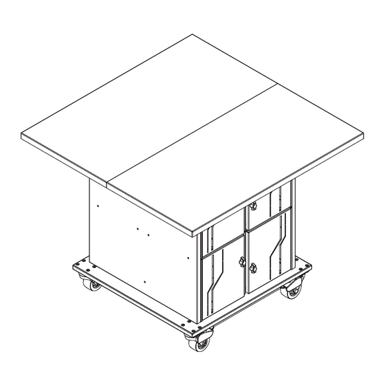
Worksurface half
min
(1) Base Assembly
LT48 Fab Lab Table
24019, 24020
7
/
"
4mm
16
45
Assembly tip: Do not tighten component fasteners completely
until all have been installed. Keeping them loose will help with
alignment between parts during assembly.
(3) 0112582
1/4-20 x 3.5"
Draw bolt
(4) 0107139
Bumper stop
door cam
(2) 0142004
Unit-to-unit
bracket
X4
(4) 0153467
Support bracket
(4) 0102297
7mm x 30mm
JCWS
(8) 026064
1/4-20 x 5/8"
PHMS
(28) 0101382
#14 x 7/8" PHSM
0191858 Page 1 of 4
Advertisement

Subscribe to Our Youtube Channel
Related Manuals for Spectrum Industries Fab Lab LT48


Summary of Contents for Spectrum Industries Fab Lab LT48
- Page 1 Assembly Instructions Assembly Instructions Important Before you begin, read and comply with all safety and operating instructions, and ensure all parts and correct quantities are included. Any parts damaged during shipment must be reported within 5 days of receipt. To report information regarding missing parts or damage, to purchase parts or accessories, or if you have any questions, please contact us.
- Page 2 Assemble worksurfaces 1. Place the worksurfaces laminate-side down onto a flat non-abrasive surface and bring the two worksurfaces together. 2. When the two worksurfaces are completely together 4. Using the pre-drilled pilot holes and (4) #14 x 7/8” PHSM (tight seam), set a draw bolt into each pocket. screws, install the (2) unit-to-unit brackets across the seam as shown (one on each end).
- Page 3 Attach support brackets 1. Align and attach the (4) support brackets to the base assembly (one on each corner) with (2) 1/4-20 x 5/8” PHM screws. The flanges will face inward. 2. Install (1) #14 x 7/8” PHSM screw into the worksurface pilot hole hole shown. Support bracket b l y s e m...
- Page 4 Bumper stop door cam Bumper stop door cam #14 x 7/8” PHSM 1500 RIVER STREET, PO BOX 400, CHIPPEWA FALLS, WI 54729 / 800-235-1262 / 715-723-6750 / WWW.SPECTRUMFURNITURE.COM © 2024 Spectrum Industries Inc., All rights reserved. 0191858 Page 4 of 4...
Need help?
Do you have a question about the Fab Lab LT48 and is the answer not in the manual?
Questions and answers