Table of Contents
Advertisement
Quick Links
DMSDG/DLSH/DCKW Series
Electric Actuator
Compact Guided Type/Gripper 2-Finger
Type/Gripper 3-Finger Type
INSTRUCTION MANUAL
Read this Instruction Manual before using the product.
In particular, read the safety notes carefully.
Keep this Instruction Manual safe for use at any time.
2024-06-25
SM-A69064-A/4
Advertisement
Table of Contents

Related Manuals for CKD DMSDG Series


Summary of Contents for CKD DMSDG Series
- Page 1 DMSDG/DLSH/DCKW Series Electric Actuator Compact Guided Type/Gripper 2-Finger Type/Gripper 3-Finger Type INSTRUCTION MANUAL Read this Instruction Manual before using the product. In particular, read the safety notes carefully. Keep this Instruction Manual safe for use at any time. 2024-06-25 SM-A69064-A/4...
-
Page 2: Preface
PREFACE Thank you for purchasing CKD's "D-Series spring drive type" electric actuator. This Instruction Manual describes basic matters related to the operation of this product in order to fully demonstrate its performance. Please read this Instruction Manual thoroughly and use the product properly. -
Page 3: Safety Information
SAFETY INFORMATION When designing and manufacturing any device incorporating the product, the manufacturer has an obligation to ensure that the device is safe. To that end, make sure that the safety of the machine mechanism of the device and the electric system that controls such mechanism is ensured. - Page 4 <Warning symbol type> A general purpose mark A mark that prohibits touching indicating prohibited (not equipment. allowed) actions. A general purpose mark A mark that prohibits the act of indicating the danger such as putting a finger. electric shock and burn. A mark indicating the danger A general purpose mark that occurs when an automatic...
-
Page 5: Precautions On Product Use
Precautions on Product Use DANGER Do not use this product for the following applications. Medical equipment pertaining to sustainment and management of human life and body Mechanism and mechanical device for transferring and transporting people Critical parts for securing safety in a mechanical device WARNING Never modify or implement additional processing to the product. -
Page 6: Table Of Contents
CONTENTS PREFACE ......................2 SAFETY INFORMATION ..................3 Precautions on Product Use ....................5 CONTENTS ......................6 1. PRODUCT OVERVIEW ..................8 System Structure ......................8 Instruction Manuals Related to This Product ............10 Part Name ........................11 Model Number Indication ..................13 2. - Page 7 Calculation of Positioning Time ................65 Index ........................66 Glossary ......................67 2024-06-25 SM-A69064-A/4...
-
Page 8: Product Overview
PRODUCT OVERVIEW System Structure Use the DMSDG/DLSH/DCKW series by connecting it to the ESC4 series controller. System Structure Surge protector Controller: ESC4 series I/O cable power supply Noise filter for power supply Motor relay cable Switch relay cable Connectable actuators DMSDG DLSH DCKW... - Page 9 The following items can be purchased from us in the system configuration. Component Product name/Model No. This product Actuator DMSDG/DLSH/DCKW series Controller ESC4 series Motor relay cable ESC3-M2-R□ Accessories Switch relay cable ESC3-S2-R□ Cylinder switch cable ESC3-SW-□ I/O cable ESC3-NP2-□ Power supply connector MC 1,5/ 4-ST-3,81 (PHOENIX CONTACT) Sold separately...
-
Page 10: Instruction Manuals Related To This Product
The instruction manuals related to this product are as follows. Controller for Electric actuators Electric Actuator SM-A69055 DSSD2 series SM-A85796 DSTK series ESC4 series DSTG series DSTS series DSTL series SM-A69064 (this Instruction Manual) DMSDG series DLSH series DCKW series 2024-06-25 SM-A69064-A/4... -
Page 11: Part Name
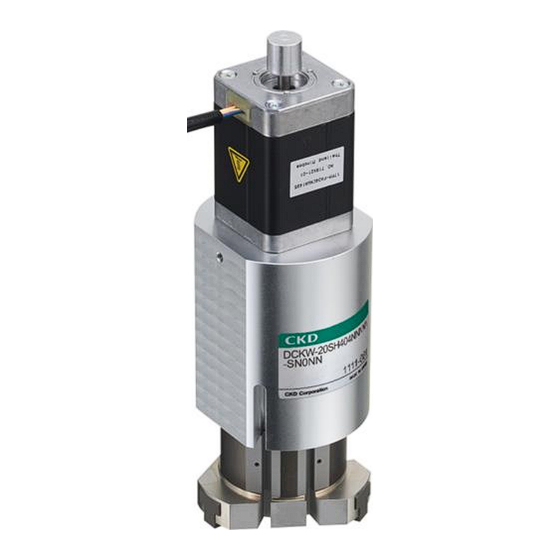
Part Name DMSDG series Manual Motor operation shaft Pullout cable Cylinder switch insertion port Body Cylinder switch DLSH series Finger Body Manual Motor operation shaft Pullout cable Cylinder switch Cylinder switch insertion port Cylinder switch insertion port 2024-06-25 SM-A69064-A/4... - Page 12 DCKW series Body Motor Manual Finger operation shaft Pullout cable Cylinder switch Cylinder switch insertion port 2024-06-25 SM-A69064-A/4...
-
Page 13: Model Number Indication
Model Number Indication ⚫ Use this product by connecting it to the ESC4 series controller. It does not work when connected to other controllers such as ECG-A/B and ECR series controllers. DMSDG series DMSDG F3PH Size IO cable length included... - Page 14 DMSDG F3PH Size IO cable length included Applicable controller Note 1 ESC4 Connector take-out 10 m direction Note 2 Spring lead 5.1 mm Bottom Right side Left side Controller Stroke length attachment Note 4 10 mm Not included 20 mm DIN rail 30 mm mounting...
- Page 15 DLSH series DLSH F3PH Size IO cable length included Applicable controller Note 1 ESC4 10 m Spring lead 4.2 mm Stroke length 10 mm Controller (5 mm per side) attachment Note 3 Not included DIN rail Rubber cover Finger mounting Basic type specifications included...
- Page 16 DLSH F3PH Size IO cable length included Applicable controller Note 1 ESC4 10 m Spring lead 6 mm Stroke length 22 mm Controller (11 mm per side) attachment Note 3 Not included DIN rail Rubber cover Finger mounting Basic type specifications included Panel mounting...
- Page 17 DCKW series DCKW F3PH Size IO cable length Applicable included controller Note 1 ESC4 Spring lead 10 m 4.2 mm Stroke length 10 mm (5 mm per side) Controller Rubber cover attachment Note 3 Switch Not included included NNNN Not included DIN rail F3PH F-type straight type...
- Page 18 DCKW F3PH Size IO cable length Applicable included controller Note 1 ESC4 Spring lead 10 m 6 mm Stroke length 8 mm (4 mm per side) Controller Rubber cover attachment Note 3 Switch Not included included NNNN Not included DIN rail F3PH F-type straight type mounting...
- Page 19 Relay cable, cylinder switch cable ◼ Motor relay cable model number system (ESC4 series) ESC3-M2-R Cable length 10 m ◼ Motor relay cable external dimensions (ESC4 series) Controller side Actuator side L (cable length is according to the model number.) ◼...
- Page 20 ◼ Cylinder switch cable model number system (ESC4 series) ESC3-SW- T3PH Switch type T3PH T-type straight type T3PV T-type L-shaped type F3PH F-type straight type F3PV F-type L-shaped type ◼ Cylinder switch cable external dimensions (ESC4 series) * When T3PH is selected Set screw (M2.5) Depending on the switch model number selection, the dotted line part will be as shown below.
-
Page 21: Installation
INSTALLATION Com mon DANGER Do not use the product in a place where dangerous substances such as ignitable, inflammable, or explosive materials are present. A fire, ignition, or explosion may occur. Do not work with wet hands. Doing so may cause electric shock. Since the control power supply and motive power supply are not insulated, never connect the + and −... - Page 22 DM S DG s er i es DANGER There is a risk of your fingers getting caught between the body and the table during operation. Com mon WARNING Do not install the product to a combustible material. If the product is installed near a combustible material, a fire may result. Do not place heavy objects on cables or pinch them.
- Page 23 WARNING Design a safety circuit or safety device so that if the machine stops due to a system abnormality such as an emergency stop or a power failure, the equipment will not be damaged or personal injury will not occur. When wiring the product, refer to this Instruction Manual or any other relevant instruction manuals to make sure that the wiring is correct and connectors are firmly connected.
- Page 24 Com mon CAUTION Do not use the product in an environment where a strong magnetic field occurs. A malfunction may occur. Do not perform a withstand voltage test or an insulation resistance test on a device with the product installed. ...
- Page 25 CAUTION When performing electric welding to the equipment to which the product is installed, remove all the frame ground connections of the product. If electric welding is performed with the frame ground connected, the product may be damaged due to welding current, excessive high voltage during welding, or surge voltage.
- Page 26 CAUTION Install the product in a way that it is not subjected to twisting or bending force. When using positioning holes, make sure to use pins having the size that does not require press-fitting. Press fitting pins may cause damage or distortion in the guide section, resulting in reduced accuracy.
- Page 27 DL SH s e ri e s CAUTION Prevent any excess load from being applied to the finger and attachment while loading/unloading the workpiece or transporting the workpiece. Scratches or dents may occur on the linear guide rolling surface of the finger, leading to malfunction.
- Page 28 DL SH /D CK W Se r ie s CAUTION Design with safety in mind. Self-lock when de-energized may not work depending on the gripping amount. The gripping force may decrease due to a power failure, etc., which may cause the workpiece to fall.
-
Page 29: Environment
10 mm or more Actuator If the actuators are adjacent to each other, the cylinder switch may malfunction. Keep the distance below from the actuator surface. ◼ DMSDG series 20 mm or more 20 mm or more Cylinder switch position 2024-06-25... - Page 30 ◼ DLSH-20 10 mm or more 10 mm or more 2024-06-25 SM-A69064-A/4...
- Page 31 ◼ DLSH-32 20 mm or more 20 mm or more ◼ DCKW series 20 mm or more 20 mm or more 2024-06-25 SM-A69064-A/4...
-
Page 32: Unpacking
Unpacking CAUTION Do not carry heavy products alone. Do not stand on the package. In order to prevent deforming the package, do not place heavy objects and objects of which their load concentrates. Do not apply unnecessary force to any part of the product. When carrying or handling the product, use extreme care not to apply impact to the product (for example, do not drop the product). -
Page 33: Installing
The flatness of the mounting surface of the body shall be 0.05 mm or less. Do not apply twisting or bending force to the product. An operation fault or damage may occur. DMSDG series ◼ For the screw-in depth and the tightening torque of bolts for installing the body, refer to the following table. - Page 34 ◼ DLSH series For the screw-in depth and the tightening torque of bolts for installing the body, refer to the following table. Tightening torque Max. screw-in depth L Item Bolt (N·m) (mm) DLSH-20 M5 × 0.8 DLSH-32 M6 × 1.0 ◼...
- Page 35 Do not apply strong impact or excessive moment to the slide table. A malfunction or damage may occur with the product. ◼ DMSDG series When fixing the table to the jig, use the appropriate tightening torque. Tightening torque Max. screw-in depth L...
- Page 36 CAUTION When mounting the attachment to the finger, take into consideration the effects exerted on the hand body and perform tightening while providing support using a tool such as a spanner so to prevent the finger from being distorted. Damage may occur. When mounting the attachment to the finger, be careful not to apply lateral load to the finger.
- Page 37 ◼ DCKW series Tighten Item Bolt Tightening torque (N·m) DCKW-20 M3 × 0.5 0.59 DCKW-32 M4 × 0.7 2024-06-25 SM-A69064-A/4...
- Page 38 Cylinder switch WARNING Never use in an explosive gas atmosphere. The cylinder switch is not explosion-proof. Never use the product in an explosive gas atmosphere as it may cause an explosion hazard. Use it correctly within the specification range. ...
- Page 39 CAUTION Observe the tightening torque when installing the cylinder switch. If the maximum tightening torque is exceeded, setscrews, brackets, switches, etc. may be damaged. In addition, if the switch is tightened with less than the minimum tightening torque, the switch mounting position may be shifted.
- Page 40 CAUTION If the switch is set to the center of the operating range, gripping force may be reduced during PUSH/closing operation. Do not use the switch lead wire to carry the cylinder. It may cause the lead wire to break or the internal elements of the switch to be damaged.
- Page 41 ◼ Cylinder switch Refer to the table below for the tightening torque when fixing to the actuator body. Item Tightening torque (N·m) 0.1 to 0.2 0.03 to 0.08 ※ To tighten the fixing screw, use a flathead screwdriver with a grip diameter of 5 to 6 mm, tip shape width of 2.4 mm or less, and thickness of 0.3 mm or less.
-
Page 42: Usage
USAGE DANGER Do not enter the operating range while the actuator can operate. An injury may occur. Do not work with wet hands. Doing so may cause electric shock. WARNING Do not climb on the product or put things on it. ... - Page 43 Com mon CAUTION When the controller and actuator are connected with a cable, do not move the actuator moving part by external force except for manual operation. A malfunction or damage may occur due to regenerative currents. Do not dent or scratch the moving part of the actuator. ...
- Page 44 CAUTION When changing the combination of the actuator and controller, be sure to check the combination before operating them. An accident may occur. Use the actuator so that no impact is applied to the moving part. Since the product life varies depending on the transfer load, etc., set it with sufficient margin.
- Page 45 DM S DG s er i es CAUTION When pressing a workpiece, use only in the PUSH direction. Applying a load in the PULL direction to the rod may cause failure. 2024-06-25 SM-A69064-A/4...
- Page 46 DL SH /D CK W Se r ie s CAUTION When gripping a workpiece, use only in the closing direction. If used in the opening direction, excessive force will be applied to the spring, causing failure. The detection range of the cylinder switch varies depending on the temperature and installation.
- Page 47 ⚫ Repeatability refers to the displacement of the finger stop position when clamping and unclamping are repeated under the same conditions. The same conditions include hand fixing and use of the same attachment, as described below. <Conditions> ◎ Attachment size, shape, and weight ◎...
-
Page 48: Usage
Usage For information on how to use the DMSDG/DLSH/DCKW series, refer to the instruction manual of the ESC4 series. For the instruction manual numbers, refer to "1.2Instruction Manuals Related to This Product". Using the Controller For information on how to use the controller, refer to the instruction manual of the ESC4 series. -
Page 49: Manual Operation
Manual Operation CAUTION Do not apply excessive torque to the manual operation shaft. An operation fault or damage may occur. Make sure that the motor is in de-energized state before operating it. A malfunction or damage may occur with the product. Manual operation is mainly used during startup, maintenance, and inspection. - Page 50 ◼ DLSH/DCKW Manual operation shaft CCW (counterclockwise): Finger opens. CW (clockwise): Finger closes. Close Open 2024-06-25 SM-A69064-A/4...
-
Page 51: Self-Lock
The DLSH and DCKW series maintain gripping force (self-lock) even when the motive power supply is de-energized during pressing and gripping. The self-lock effective range depends on the size and rotary switch setting. ⚫ The DMSDG series does not support the self-lock. Contact us if you need the self-lock. DLSH ◼... -
Page 52: Maintenance And Inspection
MAINTENANCE AND INSPECTION WARNING Do not perform disassembly or modification of products that are not specified in this manual. An injury, accident, malfunction, or failure may occur; in addition, the specifications described in this manual may not be satisfied. Do not attach or remove wires and connectors with the power turned ... -
Page 53: Periodic Inspection
DLSH lithium-based grease: AFF grease (THK Co., Ltd.) Check that there are no vibrations or abnormal Noise If there is any abnormality, contact your nearest CKD sounds while the product inspection sales office or distributor. is stopped or operated. -
Page 54: Precautions On Product Disposal
Precautions on Product Disposal CAUTION When disposing of the product, comply with “Waste Management and Public Cleansing Act” and have an industrial waste disposal company dispose of the product. 2024-06-25 SM-A69064-A/4... -
Page 55: Troubleshooting
TROUBLESHOOTING Problems, Causes, and Solutions If the product does not operate as intended, confirm the table below for a possible solution. Refer to the catalog or the instruction manual of each controller for details on how to take action. Refer to "1.2Instruction Manuals Related to This Product" for the instruction manual numbers of controllers. - Page 56 Problem Cause Solution References The input signal from the host "3.2.1 Basic Input signal is equipment may be chattering. operation" Note 1 unstable. Ensure the input signal is at least 20 msec. "2.3.3 Wiring with the I/O cable" Wiring is not correct. Check the wiring.
- Page 57 It will need to be repaired. problem occurs" damaged. Note 1 If you have any other questions or concerns, contact your nearest CKD sales office or distributor. Note 1: The reference item is "SM-A85796" in the instruction manual of the controller. 2024-06-25...
- Page 58 It will need to be repaired. damaged. problem occurs" Note 1 If you have any other questions or concerns, contact your nearest CKD sales office or distributor. Note 1: The reference item is "SM-A85796" in the instruction manual of the controller. 2024-06-25...
- Page 59 Items to check when a problem occurs Item What to check Check the controller LED display. Servo lamp Controller status Alarm lamp (red) (green) Control power OFF Motor energized state Normal Blinking Controller Motor de- (Lit once per energized state second) Blinking When an...
-
Page 60: Alarm Indications And Countermeasures
An overcurrent has flown Power cycle into the motor. Note 1: The reference item is "SM-A85796" in the instruction manual of the controller. ※ If the error reoccurs even after power cycling, contact your nearest CKD sales office or distributor. 2024-06-25 SM-A69064-A/4... -
Page 61: Warranty Provisions
If the product specified herein fails for reasons attributable to CKD within the warranty period specified below, CKD will promptly provide a replacement for the faulty product or a part thereof free of charge or repair the faulty product at one of CKD's facilities free of charge. -
Page 62: Reference Information
REFERENCE INFORMATION Specifications DMSDG series Item DMSDG-08 DMSDG-16 □20 stepping motor □28 stepping motor Motor type Drive system Cylindrical spring Stroke length Effective pressing range 5 to 15 5 to 25 5 to 15 5 to 25 Max. pressing force... - Page 63 DLSH series Item DLSH-20 DLSH-32 □28 stepping motor □42 stepping motor Motor type Drive system Cylindrical spring Stroke length 10 (5 per side) 22 (11 per side) Effective pressing range Max. gripping force (setting 9) 10 (one side) 40 (one side) Note 1 Static allowable moment MP = 2.1, MY = 2.1, MR = 2.1...
- Page 64 DCKW series Item DCKW-20 DCKW-32 □28 stepping motor □42 stepping motor Motor type Drive system Cylindrical spring Stroke length 4 (2 per side) 8 (4 per side) Effective pressing range Max. gripping force (setting 9) 8 (one side) 30 (one side) Note 1 Operating speed range 4 to 41...
- Page 65 Calculation of Positioning Time The method for calculating the positioning time of the DMSDG series is as follows. Positioning time of pressing operation Description Code Unit Formula Acceleration Deceleration Constant speed range Speed range range According to the table below...
- Page 66 Index Pressing speed range ........62 D R Drive system ........62, 63, 64 Repeatability ........47, 63, 64 E S Effective pressing range ......62, 63, 64 Self-lock ............51 G Static allowable moment ......62, 63 Gripping speed range ........63, 64 あ...
- Page 67 Glossary CAT5e EDS file A standard for network cables, also called Abbreviation for Electronic Data Sheet file. It category 5e or category 5 enhanced. The contains information to help start up, operate, and communication speed has been improved from maintain EtherNet/IP-compatible devices. Since the conventional CAT5 standard.
- Page 68 Input signal Alarm code It indicates the bit-wise data to be written from the When an error is detected, it is output from the host device (PLC, etc.) to the controller in controller to inform you of the error. You can check EtherCAT communication.
- Page 69 Portable mass Grease It indicates the maximum mass that the actuator It is applied to bearings, bearings, etc., to reduce can transfer. friction and smooth the operation of the machine. Because performance cannot Allowable thrust load demonstrated due to deterioration of grease or Limit value of the load that can be applied in the adhesion foreign...
- Page 70 Static allowable moment Software limit Limit value of the load moment that can be applied It indicates the limit of the operating range set in to the slider when the actuator is stationary. How the controller. to apply each moment in the slider type is as follows.
- Page 71 Half-duplex communication Ball screw communication method which both A mechanical element that can convert rotational transmission and reception cannot be performed motion to linear motion. Unlike sliding screws, the at the same time (only one of them can be ball rolls between the screw shaft and nut, performed).
- Page 72 Remote output It indicates bit-wise data that is written from the host device (PLC, etc.) to the controller in the communication of CC-Link specification. Remote input It indicates bit-wise data that the host device (PLC, etc.) reads out from the controller in the communication of CC-Link specification.
Need help?
Do you have a question about the DMSDG Series and is the answer not in the manual?
Questions and answers