Table of Contents
Advertisement
Quick Links
Instruction Manual
Sequential control component for pulse jet valve
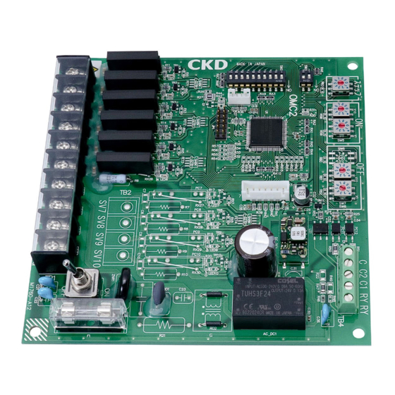
OMC2-10
OMC2-6
●
Before operating the product, read this
instruction manual without fail.
Among all, carefully read safety-related
descriptions.
●
Keep this instruction manual in a safe place so
that it can be referred to whenever necessary.
SM-50661-A
CKD Corporation
Advertisement
Table of Contents

Related Manuals for CKD OMC2-10


Summary of Contents for CKD OMC2-10
- Page 1 SM-50661-A Instruction Manual Sequential control component for pulse jet valve OMC2-10 OMC2-6 ● Before operating the product, read this instruction manual without fail. Among all, carefully read safety-related descriptions. ● Keep this instruction manual in a safe place so that it can be referred to whenever necessary.
- Page 2 SM-50661-A For safe operation of product 1. General precautions This instruction manual covers basic items related to the handling of the product including an outline of actions, control method, cable connection procedure and maintenance. Description about cable connection procedures in this instruction manual is for electricians.
-
Page 3: Table Of Contents
SM-50661-A [ Contents ] 1. Outline of Actions ---------------------------------------------------- 2. Name of Each Part --------------------------------------------------- 3. Fixing Method --------------------------------------------------------- 4. Wiring Method --------------------------------------------------------- 5. Pre-operation Check ------------------------------------------------ 6. Adequate Operation Method ------------------------------------- 7. Initial Setting and Action 7.1 Independent action --------------------------------------------- 7.2 Master/Slave action --------------------------------------------- 7.3 Specifying the number of steps ---------------------------- 7.4 Pulse ON time setting ------------------------------------------... -
Page 4: Outline Of Actions
SM-50661-A Outline of Actions The pulse jet controller conducts sequence control of pulse jet valves of the dust collector according to the number of valves. You can designate an arbitrary number of steps between 1 and 10 (1 and 6) according to the number of connected valves, and indicators show the operating valves. -
Page 5: Name Of Each Part
SM-50661-A 2. Name of Each Part ① DIP switch (SW3) Switches among the independent, master and slave actions.・・・・・・・> 8,9 ② DIP switch (SW2) Specify double hammering or interval timer. ・・・・・・・・・・・・・・・・・・・・・> 13,14 ③ LED(LED1 to 10(6)) Lights up upon a pulse. ④... -
Page 6: Fixing Method
SM-50661-A Fixing Method ! CAUTION : Install the product free from dust and water splashes. Round holes (at four places: a) are provided for the pulse jet controller as shown in Fig. 3-1. Use M4 screws to fix securely. Use accessory spacers when necessary. 4-Ø4.5(a) Accessory spacer (4 pieces) 130 (Mounting pitch) - Page 7 SM-50661-A ③ AC source voltage input and grounding ! CAUTION : Connect the grounding cable without fail to avoid electric shock. Check the voltage of the valve to be used, and connect the conforming voltage to the AC input terminals (V1 and V2). Ground 100VAC to 220VAC (Fig.
-
Page 8: Pre-Operation Check
SM-50661-A 5. Pre-operation Check 5.1 Appearance check ! CAUTION : Turn the source power off. ● Check that the pulse jet controller is securely fixed. 5.2 Wiring check ! CAUTION Turn the source power off. After checking wiring, fit the terminal cover in the original state. -
Page 9: Initial Setting And Action
SM-50661-A 7. Initial Setting and Action 7.1 Independent action ① Outline Operate the valve according to the set step with a single pulse jet controller. ② Set DIP switch (SW3) as shown in Fig. 7-1. (Use the tip of a precision regular screwdriver or the like to manipulate.) (Fig. -
Page 10: Master/Slave Action
SM-50661-A 7.2 Master/Slave action ① Outline While a single pulse jet controller can issue up to 10 output points, expansion can be made to 20 or 30 points through connection shown in Fig. 7-3. Controller No. 1 Controller No. 2 Controller No. -
Page 11: Specifying The Number Of Steps
SM-50661-A ③ Action sequence ● Turn the master and slave on simultaneously or turn the slave on first. Power supply No.1 (Master) P.8 (Fig. 7-2) No.2 (Slave) No.n (Slave) 1 cycle Power SW ON (Valve output start) (Fig. 7-5) ● SVn: Valve of the specified number of steps 7.3 Specifying the number of steps ①... -
Page 12: Pulse On Time Setting
SM-50661-A 7.4 Pulse ON time setting ① Use the DIP switch (ON) to specify the pulse ON time. (Use the tip of a precision regular screwdriver or the like.) ● Specify in the two-digit number x 0.01 seconds (time range). Example: 0.25 sec. O... -
Page 13: Pulse Off Time Setting
SM-50661-A 7.5 Pulse OFF time setting ① Use the DIP switch (OFF) to specify the pulse OFF time. (Use the tip of a precision regular screwdriver or the like.) ● Specify in the two-digit number x 1 second (time range). Example: 30 sec. -
Page 14: Double Hammering Setting
SM-50661-A 7.6 Double hammering setting ① Use DIP switch (SW2) to specify double or single hammering. Example: Double hammering at SV3 and 6 only (Fig. 7-10) ② Action sequence Double hammering Double hammering (Fig. 7-11) ● SW2 is common for "double hammering" and "interval timer" settings, and it can be used for either purpose. -
Page 15: Interval Timer Setting
SM-50661-A 7.7 Interval timer setting ① Insert jumper (J5) to specify the interval timer (pause in each cycle). (1 to 99 min.) Function of SW2 The interval timer is not accepted at Double hammering the controller operating in the slave Interval timer action mode. - Page 16 SM-50661-A ③ Action sequence ③-1. Independent action Power supply 1 cycle A: Interval timer Power SW ON (Fig. 7-14) ③-2. Master/Slave action Power supply No.1 (Master) P.8 (Fig. 7-2) No.2 (Slave) 1 cycle A: Interval timer Power SW ON (Fig. 7-15) ●...
-
Page 17: Stopping Action
SM-50661-A 7.8 Stopping action ① Short circuit across C and C2 of the terminal block (TB4) to turn off the valve output. Open to output from the next step. (Immediate stop) ON: Stop (valve output OFF) (Fig. 7-16. Immediate stop/Cycle stop in independent action mode) ON: Stop (valve output OFF) ... - Page 18 SM-50661-A ③ Insert the jumper (J1) to stop at each cycle. (Cycle stop) Stopping action Cycle stop is not accepted at the controller Immediate stop operating in the slave action mode. Cycle stop ● Connect the stop input to the master only in the master/slave action mode after cycle stop.
-
Page 19: Specifications Of Product
SM-50661-A 8. Specifications of Product Number of output steps: 6 (OMC2-6), 10 (OMC2-10) Source voltage: 100 to 220VAC ±10% 50/60Hz Current consumption: Within 5VA (controller only) Power supply fuse: 3A 250V Operating ambient temperature: -10 to +60°C Relative humidity: 30 to 80%RH Storage ambient temperature: -20 to +70°C... -
Page 20: Inspection
SM-50661-A 9. Inspection Perform periodic inspection every six months to operate the product in the best condition. For details of inspection, refer to Section 5 "Pre-operation Check." 10. Accessories The following parts are attached as accessories. Part name Model Quantity Spacer...
Need help?
Do you have a question about the OMC2-10 and is the answer not in the manual?
Questions and answers