
Related Manuals for Titan Fitness TRWM1


Summary of Contents for Titan Fitness TRWM1
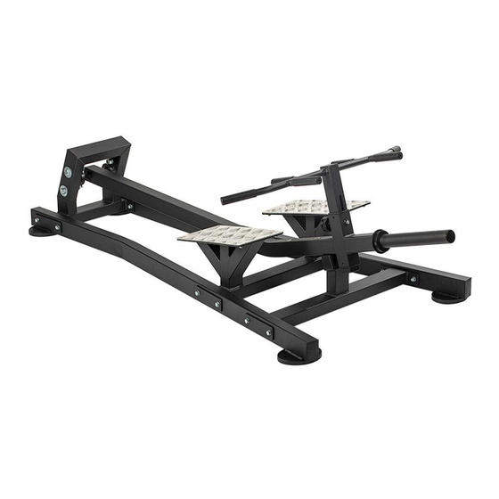
- Page 1 STANDING T-ROW MACHINE TRWM1-TRWM2 401901 Operator’s Manual Read the Operator’s Manual entirely. When you see this symbol, the subsequent instructions and warnings are serious follow without exception. Your life and the lives of others depend on it!
- Page 2 ASSEMBLY PARTS DIAGRAM / EXPLODED VIEW ASSEMBLY PARTS LIST DESCRIPTION DESCRIPTION Rear Connect Frame (18) Handlebar Grip Φ29.5*Φ24.5*115 Support Frame (19) Handlebar Grip Φ29.5*130 Movable Frame (20) Bearing UCFLU205 Handle Bar (21) Flat Washer Φ9*Φ16*1.6 Pedal Connect Bracket (22) Flat Washer Φ11*Φ20*2 Left Frame (23) Flat Washer Φ17*Φ30*3...
-
Page 3: Hardware Pack
HARDWARE PACK... - Page 4 ASSEMBLY INSTRUCTIONS Step 1 Fix Pedal connect bracket (5), Support Frame (2), Left Frame (6), Right Frame (7) and Movable Frame (3) together, using Fixing Plate (8), M10 Washer (22) and M10 Nut (26), M10*75 Hex Bolt (28). Don’t tighten bolts and nuts. Pay Attention: Make sure the Movable Frame (3) is in the center of Stopper Rubber Cover (11), then tighten the bolts and nuts (A, B&C)
- Page 5 Step 2 Fix Handle Bar (4) on Movable Frame (3).
- Page 6 ACKNOWLEDGEMENT OF RISK AND RELEASE OF LIABILITY The use of any equipment, including this one, involves the potential risk of injury. Apart from any warranty claim that might be presented for a claimed defect in material or workmanship of the product, you accept and assume full responsibility for any and all injuries, damages (both economic and non-economic), and losses of any type, which may occur, and you fully and forever release and discharge Titan, its insurers, employees, officers, directors, associates, and agents from any and all claims, demands, damages,...
- Page 7 NEED HELP? CONTACT US FIRST. 1-888-410-1503 info@titan.fitness www.titan.fitness © 2024 Titan Brands...
Need help?
Do you have a question about the TRWM1 and is the answer not in the manual?
Questions and answers