Advertisement
Quick Links
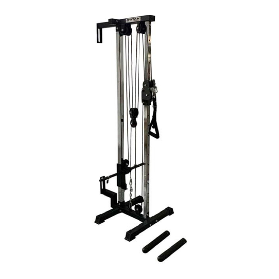
WALL MOUNTED PULLEY TOWER V3
SHPULTWRv3b, TLLPULTWRv3b
401866, 401867
Operator's Manual
Read the Operator's Manual entirely. When you see this
symbol, the subsequent instructions and warnings are
serious follow without exception. Your life and the lives
of others depend on it!
Advertisement

Subscribe to Our Youtube Channel
Related Manuals for Titan Fitness SHPULTWRv3b


Summary of Contents for Titan Fitness SHPULTWRv3b
- Page 1 WALL MOUNTED PULLEY TOWER V3 SHPULTWRv3b, TLLPULTWRv3b 401866, 401867 Operator’s Manual Read the Operator’s Manual entirely. When you see this symbol, the subsequent instructions and warnings are serious follow without exception. Your life and the lives of others depend on it!
- Page 2 PARTS DIAGRAM / EXPLODED VIEW...
- Page 3 ASSEMBLY INSTRUCTIONS...
- Page 5 ASSEMBLY INSTRUCTIONS Step 1 1.1 Push the END COVER (V) onto the end of FRONT BEAM (A) and the end of REAR BEAM (B). 1.2 Assemble the BASE FRAME (C), FRONT BEAM(A), REAR BEAM(B) and LOWER MOUNTING FRAME(G) using BOLT M10x70(4), WASHER M10(7) and NYLON NUT M10(8)
- Page 6 STEP 2 2.1 Attach the GUIDE TUBE(D) to the REAR BEAM(B) using BOLT M10x20 (1) and WASHER M10 (7). 2.2 Screw the RUBBER BUMPER (U) ON the GUIDE TUBE (D) Slide the WEIGHT CARRIAGE (J) on the GUIDE TUBE (D). 2.3 (Option I): Slide the RUBBER CUSHION(L) and SPRING CLIP(Q) onto the rod of WEIGHT CARRIAGE (1”) (J).
- Page 7 Step 3 3.1 Attach the FRONT UPRIGHT (E) to the BASE FRAME (C) using BOLT M10x50 (3), WASHER M10 (7) and NYLON NUT M10 (8). 3.2 Slide the MULTI-PULLEY BRACKET (F) onto FRONT UPRIGHT (E), screw the KNOB (P) into the MULTI-PULLEY BRACKET (F).
- Page 8 Step 4 4.1 Assemble the UPPER FIXING FRAME (H) to the FRONT UPRIGHT (E) using BOLT M10x50 (3), WASHER M10 (7) and NYLON NUT M10 (8). 4.2 Assemble the UPPER FIXING FRAME (H) to the GUIDE TUBE (D) using BOLT M10x20 (1) and WASHER M10 (7).
- Page 9 Step 5 5.1 Assemble two pcs PULLEY (M3/M7) to the MOVABLEPULLEY BRACKET (K) using BOLT M10x75 (5), WASHERM10 (7) and NYLON NUT M10 (8). 5.2 Assemble the other 11 pcs PULLEY (M1~M13, EXCEPTM3&M7) to its own BRACKET (K) using BOLTM10x45 (2), WASHER M10 (7) and NYLON NUT M10(8). (Assembly position is shown in the figure above)
- Page 10 Step 6 6. Fix the CABLE (SHORT)(S) to the MULTI-PULLEY BRACKET (F) using SAFETY HOOK (N), insert it through the bottom of PULLEY (M12), through the above of PULLEY (M13), then fix the other end of CABLE (S) to the BASE FRAME (C) using the SAFETY HOOK (N) and the CHAIN (O).
- Page 11 Step 7 7.1 Install the CABLE (LONG)(R) in the following route: Pass through the PULLEY (M1&M10), above M2, below M3, above M4, below M5 (from the same side), above M6, below M7, above M8, finally pass through M9 &M11. 7.2 Attach the DRAWSTRING(T) to the end of CABLE(LONG)(R) using the SAFETY HOOK(N) Attention: Please make sure all the cables are put in the groove of pulley and tighten all nut-and-bolt combinations before use.
- Page 12 ACKNOWLEDGEMENT OF RISK AND RELEASE OF LIABILITY The use of any equipment, including this one, involves the potential risk of injury. Apart from any warranty claim that might be presented for a claimed defect in material or workmanship of the product, you accept and assume full responsibility for any and all injuries, damages (both economic and non-economic), and losses of any type, which may occur, and you fully and forever release and discharge Titan, its insurers, employees, officers, directors, associates, and agents from any and all claims, demands, damages,...
- Page 13 NEED HELP? CONTACT US FIRST. 1-888-410-1503 info@titan.fitness www.titan.fitness © 2024 Titan Brands...
Need help?
Do you have a question about the SHPULTWRv3b and is the answer not in the manual?
Questions and answers