
Related Manuals for Bolin Technology B7-220


Summary of Contents for Bolin Technology B7-220
-
Page 1: Table Of Contents
Home ››Indoor PTZ Cameras ››Blue Line Series ››B7-220 User Guide B7-220 Indoor PTZ Camera User Guide Contents Important Information What's In The Box Optional Accessories Recommened Peripherals Overview Features Quick Start Guide Camera Diagrams & Dimensions... -
Page 2: Important Information
Before operating the unit, please read this manual thoroughly and retain it for future reference. Copyright Copyright 2015-2024 Bolin Technology, all rights reserved. No part of this manual may be copied, reproduced, translated, or distributed in any form or by any means without prior consent in writing from our company. ... -
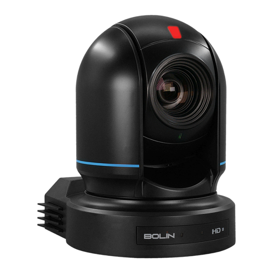
Page 3: What's In The Box
The product this manual refers to is covered by the Waste Electrical & Electronic Equipment (WEEE) Directive and must be disposed of in a responsible manner. What's In The Box B7 Series Indoor PTZ Camera (B7-220) IR Remote Controller (VCC-RC-2) RS422/232 RJ45 Adapter (VCC-CC45RS) 12V, 4A Power Supply with International Plugs (VCC-P12-4) -
Page 4: Optional Accessories
Lens Cap Optional Accessories Small PTZ Wall Mount Bracket - Available in Black or White (C-WM1B or C-WM1W) PTZ Camera Pendant Mount System for Drop Ceiling - Black or White (C-PMSB or C-PMSW) Camera Ceiling Mount Bracket - Available in Black or White (VCC-CM or VCC-CM/W) ... - Page 5 Power: 12VDC, PoE Camera Diagrams and Dimensions NOTE: All dimensions listed below are in millimeters. NOTE: All dimensions listed below are in millimeters.
-
Page 6: Quick Start Guide
Quick Start Guide The B7-220 Indoor PTZ Camera has multiple connection options for video output, power input, control input, audio input and output, and synchronization. You can choose the appropriate connection points based on your requirements. Power Options Use only the 12V DC power adapter (JEITA type4) provided with the unit. (Do not use any other DC power adapter.) POE+ (IEEE802.3at) is supported for powering the camera. -
Page 7: Video Output
2. Open an HTML5-enabled web browser on a computer and enter the IP address of the camera. By default, the camera is set to 192.168.0.13. The IP address can also be located under the “Status” menu of the camera’s On-Screen Display (OSD) or by using Bolin Technology’s IPC Search Tool in the Download Center. - Page 8 2. Once the channel has been selected, the camera should be powered on. 3. On the IR remote, the “Camera IR ID” that corresponds with the selected channel on the camera should be chosen. The remote is now ready to be used to con gure or control the camera.
- Page 9 Use RS-232 (VISCA) The RS-232 port can be utilized to connect to optional controllers, such as a joystick control keyboard or a control PC station, for camera operation. With the joystick of the control keyboard, pan/tilt and zoom operations can be performed. Preset operations can be executed using the control buttons. For operation via a PC station, application software that supports this unit is required.
- Page 10 SONY Keyboard RS422 Connection Guide for Establishing RS422 Connection and Daisy Chain Con guration for Multiple Cameras with a SONY Controller. VISCA (Non-Sony) Keyboard RS422 Connection Guide for Establishing RS422 Connection and Daisy Chain Con guration for Multiple Cameras with a Non-Sony Controller: ...
- Page 11 The included extension cables, along with the RJ45 to RS422 Phoenix connector adapter, should be utilized to establish an RS422 connection for the control device. Guide to creating an RS422 Daisy Chain Connection for Multiple Cameras with an RS422 Standard Serial Port Controller. ...
- Page 12 The extension cables that are provided, along with the RJ45 to RS422 Phoenix connector adapter, should be utilized to establish an RS422 connection for the control device. Alternatively, you can establish an RS485 connection by directly connecting the camera and the controller using a CAT5/6 T-568B Standard Ethernet cable. ...
- Page 13 VISCA over IP Using VISCA over IP allows users to control the camera from anywhere that is on the same LAN as the camera. It involves connecting the PTZ camera to a network switch. The steps are as follows: 1.
- Page 14 NOTE: Factory-Default Camera Settings for control of VISCA over IP Static IP Address: 192.168.0.13 Subnet Mask: 255.255.255.0 Gateway: 192.168.0.1 VISCA over IP Control Port: 52831 To change these settings, refer to the Web Interface Con guration section of this guide. NOTE: The VISCA over IP port of the controller MUST be set to 52381 to communicate with and control the camera. ...
- Page 15 1. On the keyboard side, connect pins 1-8. On the Video Switch side, connect pins 1-9, excluding pin 8. 2. Link keyboard pin 8 with video switch pin 9. 3. Connect keyboard pin 1 to video, switch pin 1, pin 2 to pin 2, and continue similarly (you can decide the rest based on the pattern), ensuring pin 7 is connected to pin 7.
-
Page 16: Web Interface Con Guration
2. GPI I/O Output Mode for Tally Signal Sent by Keyboard Controller: a. Connect the camera to the keyboard using a standard RS-422 control cable. b. Navigate to KEYBOARD SETTING > GPI I/O > Setting, and switch it to Output mode. Exit directly to the home menu. c. -
Page 17: Live View
Factory-Default Camera Network Settings: Static IP Address: 192.168.0.13 Subnet Mask: 255.255.255.0 Gateway: 192.168.0.1 NOTE: To obtain the IP address of the camera, open the OSD Menu and scroll down to the Status section. Alternatively, download Bolin's IPC search NOTE: To obtain the IP address of the camera, open the OSD Menu and scroll down to the Status section. Alternatively, download Bolin's IPC search tool from the website (www.bolintechnology.com) onto a Windows computer and run the tool to discover the camera on the network. - Page 18 Adjusting and Controlling PTZ Functions On the “Live View” page, the user will observe a “Menu” icon situated at the bottom right of the live view image. Additionally, on the right side of the page, there are “Pan/Tilt Controls”. This section comprises a set of arrows and sliders, speci cally designed to control the camera. The arrows are utilized to pan (move side to side) and tilt (move up and down) the camera.
-
Page 19: Fast Settings
Adjusting OSD Menu Settings from the Web Interface The OSD Menu settings can be accessed and adjusted from the Web Interface. On the “Live View” page, locate and click the “Menu” icon situated at the bottom right of the live view image to display the OSD menu. The user can navigate through these settings using the arrows under “Pan/Tilt Control”. The middle button is used to select, and the right arrow button is used to modify the setting. - Page 20 CODEC From the Codec tab, users can con gure the video streams to meet their requirements. The various settings and their functions are described below. _________________________________________________________________________________________________________________________________________________________________ OUTPUT Here you can select the HDMI/ SDI video resolution output of the camera. _________________________________________________________________________________________________________________________________________________________________ ...
-
Page 21: Image Settings
Steps to implement an on-screen overlay: 1. Begin by adding text to the title bar, such as in ‘1-Title’, then click on the checkbox located furthest to the left (which will turn red with a white check mark) to display it on the live feed image. 2. -
Page 22: White Balance
You can choose from the following modes: Full Auto, Manual, Shutter Priority, or Iris Priority. Please be aware that the parameters (such as Iris, Shutter Speed, and others) will automatically adjust according to the selected mode. You have the option to turn the Smart Exaction on or off. _________________________________________________________________________________________________________________________________________________________________ ... - Page 23 The settings allow for adjustments to the Gamma level, Contrast, Saturation, and Brightness. There is also an option to turn the Wide Dynamic Range (WDR) on on or off, along with an option for level adjustment. _________________________________________________________________________________________________________________________________________________________________ SCENE The settings include Scene presets with options for Default, Brightness, Clear, and Soft. There are Defog options with settings for Off, Auto, Manual, and Low. The Day/Night Mode has settings for Day, Night, and Auto, with sensitivity adjustments available for Low, Middle, and High levels.
-
Page 24: Color Matrix
The settings include a Mode option for Auto, Manual, and One Push White Balance. There are Zone settings available for the entire video image, or speci cally for the Top, Center, or Bottom. Near Limit adjustments can be made at distances of 1cm, 30cm, or 1 meter. Sensitivity settings can be adjusted to Low, Middle, or High levels. - Page 25 Audio Input: Mute On/Off Audio Compression setting: AAC, G711a or G711u Bit Rate selection: 30K, 40K, 48K, 64K, 96K,128K Sample Rate setting: 16K, 32K, 44.1K, and 48K Input Volume control: slider from 0 to 100. Apply settings or reset to Default settings. ...
- Page 26 The Network tab provides the following con guration options: Pattern: Choose between DHCP, which allows the camera to automatically receive an IP address from the DHCP server, or Static, which allows you to manually input an IP address. IP Address: Use the assigned IP address or manually enter a static IP address. Subnet Mask: This is determined based on the range of the IP address class.
- Page 27 TCP Port: Adjustable within a range of 1 to 65535. UDP Port: Adjustable within a range of 1 to 65535. RTSP Port: Defaulted to 554. RTSP is the protocol used for real-time video playback over the network, compatible with software like VLC Media Player. Changing the RTSP port number alters the RTSP video viewing method.
- Page 28 Navigate to the RTMP tab to stream or publish a video to a CDN (Content Delivery Network) or a cloud platform. You can obtain the URL stream and key number from an online platform such as YouTube or Twitch, usually found under Stream Settings in YouTube Studio. Stream Type: Choose between the Main or Sub Stream.
- Page 29 4. Enter the FTP server’s username and password into the ‘Server Username’ and ‘Server Password’ elds, respectively. These credentials should match those con gured on the FTP server. 5. Choose the ‘Path Type’ and ‘Path’ where you want the snapshot to be saved on the FTP server. _________________________________________________________________________________________________________________________________________________________________ ...
- Page 30 [SRT] Stream Type: Main and Sub Stream options SRT Streaming: Enable: Caller, Listener and Rendezvous selection. Caller: Set the source or destination device as the initiator of the SRT streaming session. Note, Caller mode only is sent to one receiver. 1.
- Page 31 The Device tab provides fundamental details about the PTZ camera. Device Name: You can assign a unique name to the camera and con rm by clicking Apply. You may need to share the information from this tab with the Bolin technical team, which includes the Model number, Serial number, IP Encoder Version, and AF Version.
- Page 32 Port: Enter a Port number. Refresh: Select a refresh rate time:10 Min, 30 Min, 1 Hour, 1 Day. Apply settings or click on Default to reset. _________________________________________________________________________________________________________________________________________________________________ [MAINTENANCE] Firmware Update: Click on the File Browser section and select the Firmware le update. Click on the Update button to update the PTZ camera. Device Restart: Schedule Auto Restart to: Never, Per day, Per week or Per month.
-
Page 33: Operation
Under the "Logs" tab, users can see the actions that are performed by the device. The log can be ltered by 'All', Information, Warnings, and Errors. System Menus Technical Speci cations B7-220 User Guide www.bolintechnology.com Bolin Technology System Menus...
Need help?
Do you have a question about the B7-220 and is the answer not in the manual?
Questions and answers