
Related Manuals for Renishaw UCC T5 PH20


Summary of Contents for Renishaw UCC T5 PH20
- Page 1 UCC T5 PH20 CMM controller installation guide www.renishaw.com UCC T5 PH20 CMM controller installation guide Documentation part number: H-1000-7573-07-F Issued 10 2024...
-
Page 2: Warranty
Renishaw warrants its equipment and software for a limited period (as set out in the Standard Terms and Conditions), provided that they are installed and used exactly as defined in associated Renishaw documentation. You should consult these Standard Terms and Conditions to find out the full details of your warranty. -
Page 3: Care Of Equipment
Renishaw probes and associated systems are precision tools used for obtaining precise measurements and must therefore be treated with care. Changes to Renishaw products Renishaw reserves the right to improve, change or modify its hardware or software without incurring any obligations to make changes to Renishaw equipment previously sold. Company registration details Renishaw plc. -
Page 4: Eu Declaration Of Conformity
Information to user (47 CFR 15.21) The user is cautioned that any changes or modifications not expressly approved by Renishaw plc or authorised representative could void the user's authority to operate the equipment. -
Page 5: Reach Regulation
UCC T5 PH20 CMM controller installation guide www.renishaw.com ICES-001 (Canada only) This ISM device complies with Canadian ICES-001(A) / NMB-001(A). Cet appareil ISM est conforme à la norme ICES‐001﴾A﴿ / NMB‐001﴾A﴿ du Canada. REACH regulation Information required by Article 33﴾1﴿ of Regulation ﴾EC﴿ No. 1907/2006 ﴾“REACH”﴿ relating to products containing substances of very high concern (SVHCs) is available at: www.renishaw.com/REACH... -
Page 6: Psu Electrical Ratings
UCC T5 PH20 CMM controller installation guide www.renishaw.com UCC T5 safety If the equipment is used in a manner not specified by the manufacturer, the protection provided by the equipment may be impaired. There are no user serviceable parts inside the equipment. - Page 7 UCC T5 PH20 CMM controller installation guide www.renishaw.com UCC T5 enviromental conditions Indoor use IP10* (BS EN60529:1992) Altitude Up to 2000 m Operating temperature +5 °C to +50 °C Storage temperature ‐25 °C to +70 °C Relative humidity 80% maximum ﴾non‐condensing﴿ for temperatures up to +31 °C Linear decrease to 50% at +50 °C...
-
Page 8: Renishaw Documents
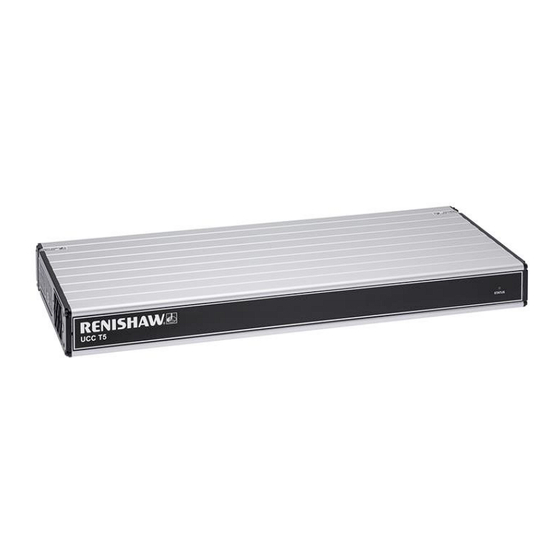
UCC T5 PH20 CMM controller installation guide www.renishaw.com UCC T5 references and associated documents It is recommended that the following documentation is referenced when installing the UCC T5: Renishaw documents Installation & user's guide: PH20 Installation guide: SPA3-2 (H-1000-5364) Installation & user's guide: MCUlite-2, MCU5-2 and MCU W-2 (H-1000-5280) - Page 9 UCC T5 PH20 CMM controller installation guide www.renishaw.com UCC T5 introduction The UCC T5 is the latest generation Renishaw CMM controller product. It replaces the UCC2 and 5-axis card in PH20 applications. Description Machine motors Machine scales and readheads Probe head - PH20 connects to UCC T5 via the orange machine cabling...
- Page 10 Please use this guide in conjunction with the PH20 user's guide in order to fully understand the system's features, capabilities and operation. The UCC T5 must be used in conjunction with a Renishaw SPA3-2. Setup and commissioning should be completed through Renishaw's UCCassist-2 software.
-
Page 11: Front Panel
UCC T5 PH20 CMM controller installation guide www.renishaw.com Front panel UCC T5 Rear panel layout Description Description 37-way D-type plug for temperature Reserved compensation Ethernet communications connector to Reserved CMM computer Reset button 15-way D-type socket for PH20 connection Reserved - (USB type B socket) -
Page 12: Stand-Alone Installation
UCC T5 PH20 CMM controller installation guide www.renishaw.com UCC T5 installation Dimensions Width Depth Height Weight 440 mm (17.3 in) 180 mm (7.1 in) 44 mm (1.7 in) 2.1 kg (4 lb 10 oz) UCC T5 can either be free standing or used in a 19 inch rack system. -
Page 13: Mounting In A 19 Inch Rack
UCC T5 PH20 CMM controller installation guide www.renishaw.com Mounting in a 19 inch rack The rack mounting kit ﴾part number A‐5518‐0005﴿ contains two brackets and four M5 × 6 mm screws. Assemble the brackets to the UCC T5 as shown below:... - Page 14 UCC T5 PH20 CMM controller installation guide www.renishaw.com UCC T5 general wiring standards To achieve reliable operation of the UCC T5 and the CMM's host computer, the following points should be observed: All signal cables MUST be screened and all cable screens must be connected electrically to the metal shells of the cable connectors...
-
Page 15: System Connection
UCC T5 PH20 CMM controller installation guide www.renishaw.com System connection Earth bonding scheme Issued 10 2024... -
Page 16: Ph20 Interconnection Diagram
UCC T5 PH20 CMM controller installation guide www.renishaw.com PH20 interconnection diagram Description PH20 orange head cable CAT 5E 300 mm cable (supplied) 16 / 0.2 mm earth connection MCU connection CAT 5E ethernet cable (5 m cross-over cable supplied) to host PC... -
Page 17: Cable Connections
It is mandatory that the Renishaw universal machine cable is used. Various lengths of cable are available and include pre-crimped options for ease of installation. The following image shows the pin numbers for each connector end view of the Renishaw universal machine cable. 15-way HDD socket pin number... - Page 18 UCC T5 PH20 CMM controller installation guide www.renishaw.com Preparation of Renishaw universal machine cable for quill mounted systems Preparation of Renishaw universal machine cable for shank mounted systems Issued 10 2024...
-
Page 19: Temperature Compensation Connector
UCC T5 PH20 CMM controller installation guide www.renishaw.com Temperature compensation connector Pin number Channel Pin number Channel Channel 1 input Channel 1 return Channel 2 input Channel 2 return Channel 3 input Channel 3 return Channel 4 input Channel 4 return... -
Page 20: Reset Button
UCC T5 PH20 CMM controller installation guide www.renishaw.com Reset button Number 3 on the rear panel is the reset button which has two different functions. The function depends on the operational state of the controller. 1. Pressing and releasing the reset button within fifteen seconds of switching on or rebooting the unit will force the controller into IP configuration state. -
Page 21: Connecting The Ucc Controller
The UCCassist-2 software must be installed on the host PC prior to connection of the UCC controller. The latest version of UCCsuite can be downloaded from the Renishaw website for anyone with a MyRenishaw account. UCCsuite will install UCCassist-2 and UCCserver to enable the hardware set-up. - Page 22 UCC T5 PH20 CMM controller installation guide www.renishaw.com IP addressing Choose an IP address for the UCC controller and an IP address for the PC's network adaptor that are of the same class: class A 1.0.0.1 – 126.255.255.254 For class A networks, a network is defined by the first number.
- Page 23 UCC T5 PH20 CMM controller installation guide www.renishaw.com Setting the IP address of the PC The process to set the IP address on the PC varies with each version of Windows. Administrator rights are needed in order to perform this operation.
- Page 24 UCC T5 PH20 CMM controller installation guide www.renishaw.com c﴿ Click on 'Properties' and select ‘Internet Protocol ﴾TCP/IPv4﴿' and click 'Properties'. d﴿ Select ‘Use the following IP address' and type in the IP address to use for the PC end of the comms link. Click in the Subnet mask field. On Windows10 the Subnet mask will already be filled in.
- Page 25 UCC T5 PH20 CMM controller installation guide www.renishaw.com Leave the 'Default gateway' field blank. Example: e) Click 'OK' and then 'OK' again. On earlier versions of Windows the PC needs to be rebooted. Issued 10 2024...
- Page 26 UCC T5 PH20 CMM controller installation guide www.renishaw.com Setting the IP address of the UCC controller The UCC controller is not intended to be used on a corporate network. It is extremely important that the setting of the IP address of the UCC controller is on a dedicated connection.
- Page 27 UCC T5 PH20 CMM controller installation guide www.renishaw.com b) Pressing 'Next' will bring up a screen to allow the specific controller to be selected. It will also give instructions on getting the controller into IP configure mode depending on if it has already been configured or has no current configuration.
- Page 28 UCC T5 PH20 CMM controller installation guide www.renishaw.com d) The UCC controller does not have an IP address. Type in the relevant address to match the network adapter in the PC. In the case below this is 10.0.0.1: e) Fill in the desired IP address. The IP configuration software has given you a head start by filling in the network part of the address appropriate for the network adapter selected (see section 'IP addressing' for a discussion of the choice and of IP addresses in general).
- Page 29 UCC T5 PH20 CMM controller installation guide www.renishaw.com f﴿ Click on ‘Configure PC and UCC pair'. If all is well this will result in the address being applied to the controller and the IP configure screen will close. If the controller is already configured a dialogue box saying the UCC is configured will open. Click 'Next' to finish.
- Page 30 UCC T5 PH20 CMM controller installation guide www.renishaw.com Downloading The name of the downloadable file is specific to the controller so the correct controller needs to be selected to select the correct downloadable. Other controller downloadables will not work on a different controller. Remember to change the name in any configuration settings appropriate for the front-end.
-
Page 31: Temperature Compensation
UCC T5 PH20 CMM controller installation guide www.renishaw.com Temperature compensation NOTE: Thermal compensation is activated and setup through UCCassist-2. Axis sensors Axis sensors are required to monitor and compensate for any temperature changes within the CMM's scale. The axis sensor is housed in a potted ring terminal with a Ø3.7 mm hole which can be screwed or glued in position using a thermally conductive glue. -
Page 32: Pin Allocation
UCC T5 PH20 CMM controller installation guide www.renishaw.com Pin allocation With the red dot on the LEMO pointing upwards: ‘Pair A' ‐ Top left pin and bottom left pin ‘Pair B' ‐ Top right and bottom right NOTE: Ensure the sensor is connected to the controller with one pin from ‘pair A' and one pin from ‘pair B'. -
Page 33: Resistance Check Procedure
Excessive humidity should be avoided Use the system as close as possible to the calibrated temperature Renishaw recommends that workpiece and axis sensors are verified at six month intervals System accuracy and calibration The TEC system can be used without calibration. The system accuracy is ±0.2 °C. -
Page 34: Testing And Verification
UCC T5 PH20 CMM controller installation guide www.renishaw.com Testing and verification The machine manufacturer or the installer of the UCC T5 is responsible for ensuring that the following testing and verification is performed to the appropriate standard: Verification that the electrical equipment is in compliance with the technical documentation... - Page 35 UCC T5 PH20 CMM controller installation guide www.renishaw.com UCC T5 troubleshooting UCC T5 visual diagnostics A visual indication of the system status is provided by a multicoloured LED on the front panel. The LED provides assistance in diagnosing system faults.
- Page 36 UCC T5 PH20 CMM controller installation guide www.renishaw.com Description No LED No power to unit. Continuous blue Unit has overheated. Continuous red Issue with comms link. Reboot unit and configure IP. Continuous green Normal operation. Slow green flash Unit waiting for download.
-
Page 37: Fatal Faults
UCC T5 PH20 CMM controller installation guide www.renishaw.com Fatal faults Situations can occur that make it inadvisable or dangerous to continue using the CMM servo system. These are known in this document and UCCassist-2 as fatal faults. A list of fatal faults are shown below and will be indicated through the user's software (for example UCCserver):... -
Page 38: Filter Replacement
UCC T5 PH20 CMM controller installation guide www.renishaw.com UCC T5 maintenance WARNING: Maintenance should only be carried out after the machine has been isolated from the electrical supply, compressed air supply or other energy sources in accordance with the machine manufacturer's instructions. - Page 39 UCC T5 PH20 CMM controller installation guide www.renishaw.com NOTE: There are no user serviceable parts inside this unit. Issued 10 2024...
- Page 40 Renishaw plc +44 (0)1453 524524 New Mills, Wotton-under-Edge +44 (0)1453 524901 Gloucestershire, GL12 8JR United Kingdom www.renishaw.com/cmmsupport For worldwide contact details, please visit our main website at www.renishaw.com/contact Issued 10 2024...
Need help?
Do you have a question about the UCC T5 PH20 and is the answer not in the manual?
Questions and answers