
Subscribe to Our Youtube Channel
Related Manuals for Renishaw UCC T3-2


Summary of Contents for Renishaw UCC T3-2
- Page 1 UCC T3-2 installation guide www.renishaw.com UCC T3-2 installation guide Documentation part number: H-1000-5254-02-D Issued 08 2019...
-
Page 2: General Information
Renishaw distributor. Warranty Renishaw plc warrants its equipment for a limited period (as set out in our Standard Terms and Conditions of Sale) provided that it is installed exactly as defined in associated Renishaw documentation. Prior consent must be obtained from Renishaw if non-Renishaw equipment (e.g. interfaces and/or cabling) is to be used or substituted. Failure to comply with this will invalidate the Renishaw warranty. -
Page 3: Care Of Equipment
Renishaw probes and associated systems are precision tools used for obtaining precise measurements and must therefore be treated with care. Changes to Renishaw products Renishaw reserves the right to improve, change or modify its hardware or software without incurring any obligations to make changes to Renishaw equipment previously sold. Packaging... -
Page 4: Product Compliance
Information to user (47 CFR 15.21) The user is cautioned that any changes or modifications not expressly approved by Renishaw plc or authorised representative could void the user's authority to operate the equipment. -
Page 5: China Rohs
UCC T3-2 installation guide www.renishaw.com China RoHS Contact Renishaw plc or visit www.renishaw.com/ChinaRoHS for the full China RoHS tabulation. Issued 08 2019... -
Page 6: Psu Electrical Ratings
Installation category II The UCC T3-2 is isolated from the ac power by disconnection of the IEC mains connector from the supplied PSU. If any additional means of isolation is required, it must be specified and fitted by the machine manufacturer or installer of the product. The isolator / disconnection device must be sited within easy reach of the operator and comply with any applicable national wiring regulations for the country of installation. -
Page 7: Enviromental Conditions
Linear decrease to 50% at +50 °C Transient voltages Installation category II Pollution degree * NOTE: It may be necessary to house UCC T3-2 in a suitable enclosure according to the installation's environmental conditions to obtain a higher IP rating. Issued 08 2019... -
Page 8: References And Associated Documents
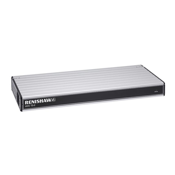
UCC T3-2 installation guide www.renishaw.com References and associated documents It is recommended that the following documentation is referenced when installing the UCC T3-2: Renishaw documents Title Document number Installation guide: PICS H-1000-5000 Installation guide: SPA3 H-1000-7566 Installation and user's guide: MCU... - Page 9 UCC T3-2 installation guide www.renishaw.com Introduction The UCC T3-2 is the latest generation Renishaw CMM controller product range. It supports the complete range of Renishaw two wire touch- trigger probes along with the high performance TP200 probe. Issued 08 2019...
- Page 10 PC - connects to UCC T3-2 via an ethernet cable The UCC T3-2 is a controller in a 19 inch rack-mountable enclosure. It is coupled to the CMM host computer by an ethernet link and to the CMM via external cable interface connectors.
-
Page 11: Front Panel Layout
UCC T3-2 installation guide www.renishaw.com Front panel layout Rear panel layout Description Connector polarity PICS SOCKET Ethernet communications connector to CMM SOCKET computer Reset button / IP configure button Reserved - do not connect SCR200 rack input (TP200) SOCKET RJ45 connector to SPA3... -
Page 12: Connecting The Ucc T3-2 To The Host Pc
It is recommended that the cross-over cable is labelled to avoid being mistaken for a non cross-over cable. Software installation UCCsuite 4.7 service pack 2 (SP2) or newer software must be installed on the host PC prior to connection of the UCC T3-2. The UCC software suite can be downloaded from the Renishaw website. -
Page 13: Ip Configure / Reset Button
UCC T3-2 installation guide www.renishaw.com IP configure / reset button Number 3 on the rear panel is the reset button which has two different functions. The function depends on the operational state of the controller. 1. Pressing and releasing the reset button within fifteen seconds of switching on or rebooting the unit will force the controller into IP configuration state. -
Page 14: Installation And Connection Details
10 mm is necessary between the sides of the unit and any potential obstruction. Mounting in a 19 inch rack The rack mounting kit ﴾Renishaw part number A‐5518‐0005﴿ contains two brackets and four M5 × 6 mm screws. Assemble the brackets to the CMM controller as shown below:... -
Page 15: Earth Bonding Scheme
UCC T3-2 installation guide www.renishaw.com Earth bonding scheme Issued 08 2019... -
Page 16: Stylus Change Rack (Scr) Connector
UCC T3-2 installation guide www.renishaw.com Stylus change rack (SCR) connector The SCR200 stylus change rack is connected to the controller via a 6-pin miniature DIN socket. The pin numbers are illustrated and their functions are shown in the table. SCR200 connector (view on rear panel) -
Page 17: Ucc T3-2 / Ucc S3 To Spa3 Connection
UCC T3-2 installation guide www.renishaw.com UCC T3-2 / UCC S3 to SPA3 connection The units must be linked by the supplied shielded CAT 5E 300 mm cable(s), no other cables are to be used. Issued 08 2019... -
Page 18: Ethernet Cable Link To Pc
UCC T3-2 installation guide www.renishaw.com Ethernet cable link to PC This is a standard ethernet CAT 5E cable, a 5 m cable is supplied as part of the CMM controller kit. Lengths up to 100 metres can be used. Issued 08 2019... -
Page 19: Pics Interface Configuration
NOTE: TP7 is not supported with this product. Cable connection Renishaw supply a short 0.3 m PICS cable (PL25) with the PHC10-3 PLUS and ACC2-3 units. This cable is designed to connect between Renishaw controllers and interfaces. A 5 m PICS cable (PL24) is available to connect the final output stage of the Renishaw system to the CMM controller. -
Page 20: Output Pin Connections
UCC T3-2 installation guide www.renishaw.com Output pin connections The pin connections for the 9‐way ‘D' type output socket are: Function STOP PPOFF ERROR SYNC HALT PDAMP LED off READ Screen Cable screen Issued 08 2019... -
Page 21: Input Pin Connections
UCC T3-2 installation guide www.renishaw.com Input pin connections The pin connections for the 9‐way ‘D' type input plug are: Function STOP PPOFF LED anode * Probe signal (input) STOP ‘pull up' PDAMP LED off * Probe signal (return) Shell Screen NOTE: LED OFF This signal passes through all products and is connected to the LED anode in the probe head or probe head controller. -
Page 22: System Interconnection Diagrams
UCC T3-2 installation guide www.renishaw.com System interconnection diagrams Standard two wired touch-trigger probe Description Head cable(s) Shielded CAT5E cable (supplied) 16 / 0.2 mm earth connection SCR200 rack connection MCU connection CAT5E cross-over cable to host PC Issued 08 2019... -
Page 23: Connecting The Ucc Controller
The UCCassist-2 software must be installed on the host PC prior to connection of the UCC controller. The latest version of UCCsuite can be downloaded from the Renishaw website for anyone with a MyRenishaw account. UCCsuite will install UCCassist-2 and UCCserver to enable the hardware set-up. - Page 24 UCC T3-2 installation guide www.renishaw.com IP addressing Choose an IP address for the UCC controller and an IP address for the PC's network adaptor that are of the same class: class A 1.0.0.1 – 126.255.255.254 For class A networks, a network is defined by the first number.
- Page 25 UCC T3-2 installation guide www.renishaw.com Setting the IP address of the PC The process to set the IP address on the PC varies with each version of Windows. Administrator rights are needed in order to perform this operation. a) Navigate to 'Control Panel', then select 'Network and sharing centre':...
- Page 26 UCC T3-2 installation guide www.renishaw.com c﴿ Click on 'Properties' and select ‘Internet Protocol ﴾TCP/IPv4﴿' and click 'Properties'. d﴿ Select ‘Use the following IP address' and type in the IP address to use for the PC end of the comms link. Click in the Subnet mask field. On Windows10 the Subnet mask will already be filled in.
- Page 27 UCC T3-2 installation guide www.renishaw.com e) Click 'OK' and then 'OK' again. On earlier versions of Windows the PC needs to be rebooted. Setting the IP address of the UCC controller The UCC controller is not intended to be used on a corporate network. It is extremely important that the setting of the IP address of the UCC controller is on a dedicated connection.
- Page 28 UCC T3-2 installation guide www.renishaw.com b) Pressing 'Next' will bring up a screen to allow the specific controller to be selected. It will also give instructions on getting the controller into IP configure mode depending on if it has already been configured or has no current configuration.
- Page 29 UCC T3-2 installation guide www.renishaw.com d) The UCC controller does not have an IP address. Type in the relevant address to match the network adapter in the PC. In the case below this is 10.0.0.1: e) Fill in the desired IP address. The IP configuration software has given you a head start by filling in the network part of the address appropriate for the network adapter selected (see section 'IP addressing' for a discussion of the choice and of IP addresses in general).
- Page 30 UCC T3-2 installation guide www.renishaw.com f﴿ Click on ‘Configure PC and UCC pair'. If all is well this will result in the address being applied to the controller and the IP configure screen will close. If the controller is already configured a dialogue box saying the UCC is configured will open. Click 'Next' to finish.
- Page 31 UCC T3-2 installation guide www.renishaw.com Changing the IP address of the UCC If the UCC controller already has an IP address, after booting up it skips its IP configuration state and proceeds into waiting for a download, shown by the status LED flashing slowly. There are two ways to force the UCC controller into its IP configuration state: a) During the 15 second power up phase, before the error LED comes on, press and release the 'Reset' button on the rear of the UCC controller.
-
Page 32: Troubleshooting
UCC T3-2 installation guide www.renishaw.com Troubleshooting Front panel LEDs UCC T3-2 visual diagnostics LED status key: Description LED on LED flashing off / on LED flashing green / red LED off LED flashing red / blue Issued 08 2019... - Page 33 Renishaw NOTE: A scale error will cause the UCC T3-2 to enter an error state which is not recoverable within a metrology application environment. If a scale error occurs it will be necessary to reinitialise the installation due to the possibility of lost scale counts and metrology being effected.
-
Page 34: Maintenance
UCC T3-2 installation guide www.renishaw.com Maintenance WARNING: Maintenance should only be carried out after the machine has been isolated from the electrical supply, compressed air supply or other energy sources in accordance with the machine manufacturer's instructions. Periodically check that all mounting screws and electrical connectors are securely tightened. Electrical safety checks should include inspecting the mains cable for damage and the safety of the connections. - Page 35 UCC T3-2 installation guide www.renishaw.com NOTE: There are no user serviceable parts inside this unit. Issued 08 2019...
- Page 36 Renishaw plc +44 (0)1453 524524 New Mills, Wotton-under-Edge, +44 (0)1453 524901 Gloucestershire, GL12 8JR United Kingdom www.renishaw.com/cmmsupport For worldwide contact details, please visit our main website at www.renishaw.com/contact Issued 08 2019...
Need help?
Do you have a question about the UCC T3-2 and is the answer not in the manual?
Questions and answers