D-Link xStack DGS-3200-10 User Manual
Xstack dgs-3200 series layer 2 managed gigabit ethernet switch
Hide thumbs
Also See for xStack DGS-3200-10:
- Specifications (5 pages) ,
- User manual (273 pages) ,
- Hardware installation manual (79 pages)

Subscribe to Our Youtube Channel
Related Manuals for D-Link xStack DGS-3200-10


Summary of Contents for D-Link xStack DGS-3200-10
- Page 1 Manual ® DGS-3200 Series Product Model: xStack Layer 2 Managed Gigabit Ethernet Switch Release 1.5...
- Page 2 Corporation. Other trademarks and trade names may be used in this document to refer to either the entities claiming the marks and names or their products. D-Link Corporation disclaims any proprietary interest in trademarks and trade names other than its own.
-
Page 3: Table Of Contents
® xStack DGS-3200 Series Layer 2 Gigabit Ethernet Managed Switch Table of Contents Intended Readers................................... ix Typographical Conventions ...................................ix Notes, Notices, and Cautions ................................. x Safety Cautions .......................................x General Precautions for Rack-Mountable Products ............................xi Lithium Battery Precaution..................................xiii Protecting Against Electrostatic Discharge ..............................xiii Web-based Switch Configuration........................1 Introduction.................................... - Page 4 ® xStack DGS-3200 Series Layer 2 Gigabit Ethernet Managed Switch Telnet Settings....................................27 Password Encryption..................................27 CLI Paging Settings ..................................28 Firmware Information .................................. 28 Power Saving Settings.................................. 30 Dual Configuration Settings................................. 31 SMTP Settings ..................................... 33 Ping Test ...................................... 34 SNTP Settings ....................................
- Page 5 ® xStack DGS-3200 Series Layer 2 Gigabit Ethernet Managed Switch PVID Auto Assign Settings ................................. 79 Port Trunking ....................................80 VLAN Trunk Settings .................................. 83 LACP Port Settings..................................84 Traffic Segmentation..................................85 IGMP Snooping ................................... 85 IGMP Snooping Settings ....................................85 Data Driven Learning Settings..................................89 ISM VLAN Settings......................................90 Restrictions and Provisos..................................90...
- Page 6 ® xStack DGS-3200 Series Layer 2 Gigabit Ethernet Managed Switch Port Lock Entries ......................................132 DHCP Server Screening................................133 DHCP Screening Port Settings..................................133 DHCP Offer Filtering....................................134 Guest VLAN ....................................135 802.1X (Port-based and Host-based Access Control) ........................ 136 Authentication Server ....................................137 Authenticator ......................................137 Client ........................................138 Authentication Process ..................................138...
- Page 7 ® xStack DGS-3200 Series Layer 2 Gigabit Ethernet Managed Switch Multiple Authentication Settings ................................177 Guest VLAN .......................................178 IGMP Access Control Settings (IGMP Authentication) ......................179 ARP Spoofing Prevention Settings ............................180 ACL ................................181 ACL Configuration Wizard................................ 181 Access Profile List ..................................182 CPU Access Profile List................................
- Page 8 ® xStack DGS-3200 Series Layer 2 Gigabit Ethernet Managed Switch Save Log ....................................251 Save All...................................... 252 Download Configuration File/Download Configuration File to NV-RAM ................252 Download Configuration File to SD Card..........................253 Download Firmware/Download Firmware to NV-RAM ......................253 Download Firmware to SD Card..............................
-
Page 9: Intended Readers
® xStack DGS-3200 Series Layer 2 Gigabit Ethernet Managed Switch Intended Readers The DGS-3200 Series Manual contains i nformation for set up an d m anagement of t he Switch. This m anual i s i ntended for network managers familiar with network management concepts and terminology. Typographical Conventions Convention Description... -
Page 10: Notes, Notices, And Cautions
® xStack DGS-3200 Series Layer 2 Gigabit Ethernet Managed Switch Notes, Notices, and Cautions A NOTE indicates important information that helps make better use of the device. A NOTICE indicates either potential damage to hardware or loss of data and tells how to avoid the problem. A CAUTION indicates a potential for property damage, personal injury, or death. -
Page 11: General Precautions For Rack-Mountable Products
® xStack DGS-3200 Series Layer 2 Gigabit Ethernet Managed Switch Do not push any objects into the openings of the system. Doing so can cause fire or el ectric shock by shorting out interior components. Use the product only with approved equipment. ... - Page 12 An energy hazard will exist if the safety ground cable is omitted or disconnected. CAUTION: When mounting the Switch on a cement wall, a proper concrete sleeve anchor should be used, such as the one that is included in the optional D-Link Wall Mount kit (DRE-KIT018).
-
Page 13: Lithium Battery Precaution
® xStack DGS-3200 Series Layer 2 Gigabit Ethernet Managed Switch Lithium Battery Precaution CAUTION: Incorrectly replacing the lithium battery of the Switch may cause the battery to explode. Replace this battery only with the same or equivalent type recommended by the manufacturer. -
Page 14: Web-Based Switch Configuration
® xStack DGS-3200 Series Layer 2 Gigabit Ethernet Managed Switch Section 1 Web-based Switch Configuration Introduction Logging onto the Web Manager Web-Based User Interface Introduction All software functions of the Switch can be managed, configured, and monitored via the embedded web-based (HTML) interface. Manage the Switch from remote stations anywhere on the network through a standard browser, such as Internet Explorer 5.5 or later, Net scape 8. -
Page 15: Web-Based User Interface
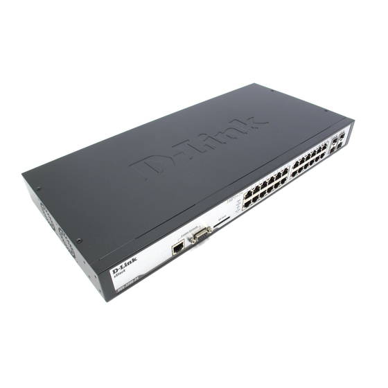
Presents a graphical near real-time image of the front panel of the Switch. This area displays the Area 2 Switch's ports and expansion modules and shows port activity, depending on the specified mode. Some management functions, including port monitoring are accessible here. Click the D-Link logo to go to the D-Link website. Area 3 Presents Switch status based on user selection and the entry of configuration data. -
Page 16: Web Pages
® xStack DGS-3200 Series Layer 2 Gigabit Ethernet Managed Switch Web Pages When connecting to the management mode of the Switch with a Web browser, a login screen is displayed. Enter a user name and password to access the Switch's management mode. Below is a list of the folders and windows available in the Web interface: Configuration –... - Page 17 ® xStack DGS-3200 Series Layer 2 Gigabit Ethernet Managed Switch NOTE: Be sure to configure the user name and password in the User Accounts window before connecting the Switch to the greater network.
-
Page 18: Configuration
® xStack DGS-3200 Series Layer 2 Gigabit Ethernet Managed Switch Section 2 Configuration Device Information System Information Serial Port Settings IP Address IPv6 Interface Settings IPv6 Route Table IPv6 Neighbor Settings Port Configuration Static ARP Settings User Accounts System Log Configuration System Severity Settings DHCP/BOOTP Relay DHCP Local Relay Settings... -
Page 19: Device Information
® xStack DGS-3200 Series Layer 2 Gigabit Ethernet Managed Switch Device Information This window contains the main settings for all major functions for the Switch. It appears automatically when you log on to the Switch. To retu rn to the Device I nformation w indow af ter v iewing oth er windows, click th e DGS-3200-10/DGS-3200-16/ DGS-3200-24 folder. -
Page 20: System Information
® xStack DGS-3200 Series Layer 2 Gigabit Ethernet Managed Switch System Information The user can enter a System Name, System Location, and System Contact to aid in defining the Switch. To view the following window, click Configuration > System Information: Figure 2- 2. -
Page 21: Serial Port Settings
® xStack DGS-3200 Series Layer 2 Gigabit Ethernet Managed Switch Serial Port Settings The user can adjust the Baud Rate and the Auto Logout values. To view the following window, click Configuration > Serial Port Settings: Figure 2- 3. Serial Port Settings window Baud Rate This field specifies the baud rate for the serial port on the Switch. - Page 22 ® xStack DGS-3200 Series Layer 2 Gigabit Ethernet Managed Switch NOTE: The Switch’s factory default IP address is 10.90.90.90 with a subnet mask of 255.0.0.0 and a default gateway of 0.0.0.0. To use the DHCP or BOOTP protocols to assign the Switch an IP address, subnet mask, and default gateway address: Use the radio button at the top of the window to choose either DHCP or BOOTP.
-
Page 23: Setting The Switch's Ip Address Using The Console Interface
® xStack DGS-3200 Series Layer 2 Gigabit Ethernet Managed Switch Setting the Switch’s IP Address using the Console Interface Each Switch must be assi gned its own IP Address, which is used for communication with an SNMP network manager or other TCP/IP application (for example BOOTP, TFTP). - Page 24 ® xStack DGS-3200 Series Layer 2 Gigabit Ethernet Managed Switch To modify an IPv6 Interface Table entry, click the corresponding Edit button. The following window opens: Figure 2- 6. IPv6 Interface Settings (Edit) window The IPv6 window i s divided i nto t hree distinct pa rts. The f ollowing parameters may b e co nfigured or viewed at the t op of t he window: Parameter Description...
-
Page 25: Ipv6 Route Table
® xStack DGS-3200 Series Layer 2 Gigabit Ethernet Managed Switch IPv6 Route Table The user can configure the Switch’s IPv6 Route Table. To view the following window, click Configuration > IPv6 Route Table: Figure 2- 7. IPv6 Route Table window Enter an IPv6 address in the Gateway field and click the Create button. -
Page 26: Ipv6 Neighbor Settings
® xStack DGS-3200 Series Layer 2 Gigabit Ethernet Managed Switch IPv6 Neighbor Settings The user can configure the Switch’s IPv6 neighbor settings. The Switch’s cu rrent IPv6 neighbor settings will b e displayed in the table at the bottom of this window. To view the following window, click Configuration >... -
Page 27: Port Configuration
® xStack DGS-3200 Series Layer 2 Gigabit Ethernet Managed Switch Port Configuration The Port Configuration folder contains three windows: Port Settings, Port Description, and Port Error Disabled. Port Settings To view the following window, click Configuration > Port Configuration > Port Settings: Figure 2- 9. -
Page 28: Port Description
® xStack DGS-3200 Series Layer 2 Gigabit Ethernet Managed Switch Address Enable or disable MAC address learning for the selected ports. When Enabled, destination and Learning source MAC addresses are automatically listed in the forwarding table. When address learning is Disabled, MAC addresses must be manually entered into the forwarding table. This is sometimes done for reasons of security or efficiency. -
Page 29: Port Error Disabled
® xStack DGS-3200 Series Layer 2 Gigabit Ethernet Managed Switch Port Error Disabled The following window will display the information about ports that have had their connection status disabled, for reasons such as storm control or link down status. To view the following window, click Configuration > Port Configuration > Port Error Disabled: Figure 2- 11. - Page 30 ® xStack DGS-3200 Series Layer 2 Gigabit Ethernet Managed Switch After entering the IP Address and MAC Address of the Static ARP entry, click Apply to implement the new entry. To completely clear the static ARP entries, click the Delete All button. To modify a st atic ARP en try, click the Edit button located on the right side of the en try in the ARP table at th e bottom of the window.
-
Page 31: User Accounts
® xStack DGS-3200 Series Layer 2 Gigabit Ethernet Managed Switch User Accounts The Switch allows the control of user privileges. To view the following window, click Configuration > User Accounts: Figure 2- 13. User Accounts window To add a new user, type in a User Name and New Password and retype the same password in the Confirm New Pass word field. Choose the level of privilege (Admin or User) from the Access Right drop-down menu. -
Page 32: System Log Configuration
® xStack DGS-3200 Series Layer 2 Gigabit Ethernet Managed Switch Management Admin User Configuration Read-only Network Monitoring Read-only Community Strings and Trap Stations Read-only Update Firmware and Configuration Files System Utilities Factory Reset User Account Management Add/Update/Delete User Accounts View User Accounts System Log Configuration The System Log Configuration folder contains two windows: System Log Settings and System Log Host. -
Page 33: System Log Host
® xStack DGS-3200 Series Layer 2 Gigabit Ethernet Managed Switch System Log Host The Switch can send Syslog messages to up to four designated servers using the System Log Server. To view the following window, click Configuration > System Log Configuration > System Log Host: Figure 2- 16. -
Page 34: Dhcp/Bootp Relay
® xStack DGS-3200 Series Layer 2 Gigabit Ethernet Managed Switch Parameter Description System Severity Choose how the alerts are used from the drop-down menu. Select Log to send the alert of the Severity Type configured to the Switch’s log for analysis. Choose Trap to send it to an SNMP agent for analysis, or select All to send the chosen alert type to an SNMP agent and the Switch’s log for analysis. - Page 35 ® xStack DGS-3200 Series Layer 2 Gigabit Ethernet Managed Switch DHCP Relay Agent This field can be toggled between Enabled and Disabled using the drop-down menu. It is Information Option 82 used to enable or disable the DHCP Relay Agent Information Option 82 on the Switch. The State default is Disabled.
- Page 36 ® xStack DGS-3200 Series Layer 2 Gigabit Ethernet Managed Switch Implementation of DHCP Relay Agent Information Option 82 The config dhcp_relay opti on_82 command configures the DHCP relay ag ent information option 82 setting of the Switch . The formats for the circuit ID sub-option and the remote ID sub-option are as follows: NOTE: For the circuit ID sub-option of a standalone switch, the module field is always zero.
-
Page 37: Dhcp/Bootp Relay Interface Settings
® xStack DGS-3200 Series Layer 2 Gigabit Ethernet Managed Switch DHCP/BOOTP Relay Interface Settings Users can set up a server, by IP address, for relaying DHCP/BOOTP information to the Switch. Th e user may enter a previ ously configured IP interface on the Switch th at will b e con nected d irectly to the DHCP/BOOTP serv er u sing this wind ow. Prop erly configured settings will be di splayed i n the DHCP/BOOTP Re lay Interface Table at t he bottom of t he window, once the user clicks the Apply button. -
Page 38: Dhcp Auto Configuration Settings
® xStack DGS-3200 Series Layer 2 Gigabit Ethernet Managed Switch Parameter Description DHCP Local Enable or disable the DHCP Local Relay Global State. The default is Disabled. Relay Global State This is the VLAN Name that identifies the VLAN the user wishes to apply the DHCP Local Relay VLAN Name operation. -
Page 39: Mac Address Aging Time
® xStack DGS-3200 Series Layer 2 Gigabit Ethernet Managed Switch MAC Address Aging Time Users can configure the MAC Address aging time on the Switch. To view the following window, click Configuration > MAC Address Aging Time: Figure 2 – 23. MAC Address Aging Time window Enter a value between 10 and 875 seconds. -
Page 40: Telnet Settings
® xStack DGS-3200 Series Layer 2 Gigabit Ethernet Managed Switch Telnet Settings Users can configure Telnet Settings on the Switch. To view the following window, click Configuration > Telnet Settings: Figure 2 – 25. Telnet Settings window The following parameters may be configured or viewed: Parameter Description Telnet Status... -
Page 41: Cli Paging Settings
® xStack DGS-3200 Series Layer 2 Gigabit Ethernet Managed Switch CLI Paging Settings Users can stop the scrolling of multiple pages beyond the limits of the console when using the Command Line Interface. To view the following window, click Configuration > CLI Paging Settings: Figure 2 –... - Page 42 ® xStack DGS-3200 Series Layer 2 Gigabit Ethernet Managed Switch Figure 2 – 29. Firmware Information window (DGS-3200-24 model) The following parameters may be configured or viewed: Parameter Description States the image ID number of the firmware in the Switch’s memory. The Switch can store 2 firmware images for use.
-
Page 43: Power Saving Settings
® xStack DGS-3200 Series Layer 2 Gigabit Ethernet Managed Switch Power Saving Settings This window allows the user to implement the Switch’s built-in power saving features. When the Power Saving State is Enabled, a port which has a link down status will be turned off to save power to the Switch. This will not affect the port’s capabilities when the port status is link up. -
Page 44: Dual Configuration Settings
® xStack DGS-3200 Series Layer 2 Gigabit Ethernet Managed Switch Dual Configuration Settings Users can display dual configuration settings on the Switch. The Switch allows two configurations to be stored in its memory and either can be configured as the boot-up configuration for the Switch (the DGS-3200-24 also allows configurations to be stored on an SD-card). - Page 45 ® xStack DGS-3200 Series Layer 2 Gigabit Ethernet Managed Switch Update Time States the specific time the configuration version was downloaded to the Switch. From States the IP address of the origin of the configuration. There are five ways a configuration may be downloaded to the Switch.
-
Page 46: Smtp Settings
® xStack DGS-3200 Series Layer 2 Gigabit Ethernet Managed Switch SMTP Settings SMTP or Simple Mail Transfer Protocol is a function of the Switch that will send switch events to mail recipients based on e-mail addresses entered in the wi ndow below. The Switch is t o be configured as a client of SMTP while the server is a remote device that will receive messages from the Switch, place the appropriate information into an e-mail and deliver it to recipients configured on the Switch. -
Page 47: Ping Test
® xStack DGS-3200 Series Layer 2 Gigabit Ethernet Managed Switch Ping Test Users can Ping either an IPv4 address or an IPv6 address. Ping is a small program that sends ICMP Echo packets to the IP address you s pecify. T he destination node t hen res ponds t o or “ec hoes” the packets sent f rom the Switch. This i s very useful t o ve rify connectivity between the Switch and other nodes on the network. -
Page 48: Sntp Settings
® xStack DGS-3200 Series Layer 2 Gigabit Ethernet Managed Switch SNTP Settings SNTP or Simple Network Time Protocol is used by the Switch to synchronize the clock of the computer. The SNTP Settings folder contains two windows: Time Settings and TimeZone Settings. Time Settings Users can configure the time settings for the Switch. -
Page 49: Time Zone Settings
® xStack DGS-3200 Series Layer 2 Gigabit Ethernet Managed Switch Time Zone Settings Users can configure time zones and Daylight Savings Time settings for SNTP. To view the following window, click Configuration > SNTP Settings > Time Zone Settings: Figure 2 - 36. Time Zone Settings window The following parameters can be set: Parameter Description... -
Page 50: Mac Notification Settings
® xStack DGS-3200 Series Layer 2 Gigabit Ethernet Managed Switch To: Day Of Week Enter the day of the week that DST will end. To: Month Enter the month that DST will end. To: Time In HH:MM Enter the time DST will end. DST Annual Settings –... -
Page 51: Mac Notification Port Settings
® xStack DGS-3200 Series Layer 2 Gigabit Ethernet Managed Switch MAC Notification Port Settings Users can set MAC notification for individual ports on the Switch. To view the following window, click Configuration > MAC Notification Settings > MAC Notification Port Settings: Figure 2 - 38. -
Page 52: Snmp Settings
® xStack DGS-3200 Series Layer 2 Gigabit Ethernet Managed Switch SNMP Settings Simple Network Management Protocol (SNMP) is an OSI Layer 7 (Application Layer) designed specifically for managing and monitoring network devices. SNMP enables network management stations to read and modify the settings of gateways, routers, switches, a nd other net work devices. -
Page 53: Snmp Global State Settings
® xStack DGS-3200 Series Layer 2 Gigabit Ethernet Managed Switch SNMP Global State Settings SNMP global state settings can be enabled or disabled. To view the following window, click Configuration > SNMP Settings > SNMP Global State Settings: Figure 2 - 39. SNMP Global State Settings window Click the Apply button to let your change take effect. -
Page 54: Snmp View Table
® xStack DGS-3200 Series Layer 2 Gigabit Ethernet Managed Switch SNMP View Table Users can assign views to community strings that define which MIB objects can be accessed by a remote SNMP manager. To view the following window, click Configuration > SNMP Settings > SNMP View Table: Figure 2 - 41. -
Page 55: Snmp Group Table
® xStack DGS-3200 Series Layer 2 Gigabit Ethernet Managed Switch SNMP Group Table An SNMP G roup c reated with t his t able maps SNM P u sers (i dentified in th e SNMP User Tab le) t o the views created in the previous window. -
Page 56: Snmp User Table
® xStack DGS-3200 Series Layer 2 Gigabit Ethernet Managed Switch To implement your new settings, click Apply. SNMP User Table This window displays all of the SNMP User’s currently configured on the Switch. To view the following window, click Configuration > SNMP User Table: Figure 2 - 43. -
Page 57: Snmp Community Table
® xStack DGS-3200 Series Layer 2 Gigabit Ethernet Managed Switch SNMP Community Table Users can create an SNMP community string to define the relationship between the SNMP manager and an agent. The community string acts like a password to permit access to the a gent on the Switch. One or m ore of the fo llowing c haracteristics can be associated with the community string: ... -
Page 58: Snmp Host Table
® xStack DGS-3200 Series Layer 2 Gigabit Ethernet Managed Switch SNMP Host Table Users can set up SNMP trap recipients for IPv4. To view the following window, click Configuration > SNMP Settings > SNMP Host Table: Figure 2 - 45. SNMP Host Table window To add a new entry to the Switch’s SNMP Ho st Table, enter the information at the top of the window and then click the Apply button. -
Page 59: Snmp V6Host Table
® xStack DGS-3200 Series Layer 2 Gigabit Ethernet Managed Switch SNMP v6Host Table Users can set up SNMP trap recipients for IPv6. To view the following window, click Configuration > SNMP Settings > SNMP v6Host Table: Figure 2 - 46. SNMP v6Host Table window To add a new entry to the Switch’s SNMP v6Host Table, enter the information at the top of the window and then click the Apply button. -
Page 60: Snmp Engine Id
SNMP management private enterprise number as assigned by IANA (D-Link is 171). The fifth octet is 03 to indicate the rest is the MAC address of this device. The sixth to eleventh octets is the MAC address. -
Page 61: Rmon
VRRP, or All). Click Apply when finished. Single IP Management Simply put, D-Link Single IP Management is a co ncept that will stack switches together over Ethernet instead of using stacking ports or modules. There are some advantages in implementing the “Single IP Management” feature: 1. - Page 62 ® xStack DGS-3200 Series Layer 2 Gigabit Ethernet Managed Switch There are three classifications for switches using SIM. The Commander Switch (CS) , which is the master switch of the group, Member Switch (MS), which is a sw itch t hat i s r ecognized by the CS a member of a SIM group, an d a Candidate Switch (CaS), which is a Switch that has a physical link to the SIM group but has not been recognized by the CS as a member of the SIM group.
-
Page 63: Single Ip Settings
® xStack DGS-3200 Series Layer 2 Gigabit Ethernet Managed Switch When a CaS becomes a MS, it autom atically becomes a m ember of t he first SNMP community (including read/write and rea d only) to which th e CS b elongs. However, if a MS h as its own IP ad dress, it can belong to SNMP co mmunities to wh ich other switches in the group, including the CS, do not belong. - Page 64 ® xStack DGS-3200 Series Layer 2 Gigabit Ethernet Managed Switch Figure 2 - 52. Single IP Settings window for Candidate (Enabled) Parameter Description SIM State Use the drop-down menu to either enable or disable the SIM state on the Switch. Disabled will render all SIM functions on the Switch inoperable.
-
Page 65: Topology
® xStack DGS-3200 Series Layer 2 Gigabit Ethernet Managed Switch Topology This window will be used to configure and manage the Switch within the SIM group and requires Java script to function properly on your computer. The Java Runtime Environment on your server should initiate and lead you to the Topology window, as seen below. Figure 2 - 54. - Page 66 ® xStack DGS-3200 Series Layer 2 Gigabit Ethernet Managed Switch Figure 2 - 55. Topology View window This window will display how the devices within the Single IP Management Group connect to other groups and devices. Possible icons on this window are as follows: Icon Description Group...
-
Page 67: Tool Tips
® xStack DGS-3200 Series Layer 2 Gigabit Ethernet Managed Switch Tool Tips In the Topology view window, the mouse plays an important role in configuration and in viewing device information. Setting the mouse cursor over a specific device in the topology window (tool tip) will display the same information about a specific device as the Tree view does. -
Page 68: Group Icon
® xStack DGS-3200 Series Layer 2 Gigabit Ethernet Managed Switch Group Icon Figure 2 - 58. Right-Clicking a Group Icon The following options may appear for the user to configure: Collapse – To collapse the group that will be represented by a single icon. ... -
Page 69: Commander Switch Icon
® xStack DGS-3200 Series Layer 2 Gigabit Ethernet Managed Switch Commander Switch Icon Figure 2 - 60. Right-Clicking a Commander Icon The following options may appear for the user to configure: Collapse – To collapse the group that will be represented by a single icon. Expand –... -
Page 70: Menu Bar
® xStack DGS-3200 Series Layer 2 Gigabit Ethernet Managed Switch Add to group – Add a candidate to a group. Clicking this option will reveal the following dialog box for the user to enter a password for au thentication fro m the Candidate Switch befo re being ad ded to th e SI M group. Click OK t o enter th e password or Cancel to exit the dialog box. -
Page 71: Firmware Upgrade
® xStack DGS-3200 Series Layer 2 Gigabit Ethernet Managed Switch Firmware Upgrade The Commander Switch may be used for firmware upgrades of member switches. Member Switches will be listed in the table and will be specified by Port (port o n the CS wh ere the MS resides), MAC Address, Model Nam e and Version. To specify a certain Switch for firmware download, click its corresponding check box under the Port heading. -
Page 72: Sd Card Fs Settings
® xStack DGS-3200 Series Layer 2 Gigabit Ethernet Managed Switch SD Card FS Settings Users can plug an SD f lash car d i nto a front sl ot on th e D GS-3200-24 ( DGS-3200-10 and DGS-3200-16 do no t support th is feature). - Page 73 ® xStack DGS-3200 Series Layer 2 Gigabit Ethernet Managed Switch Format If you have inserted a new SD Flash card this button will appear. Click this button to format the new SD Flash card. Copy to Click this button to copy a file to another location. Move to Click this button to move a file to another location.
-
Page 74: L2 Features
® xStack DGS-3200 Series Layer 2 Gigabit Ethernet Managed Switch Section 3 L2 Features Jumbo Frame Egress Filter Settings 802.1Q VLAN Private VLAN Settings 802.1v Protocol VLAN MAC-based VLAN Settings GVRP Settings PVID Auto Assign Settings Port Trunking VLAN Trunk Settings LACP Port Settings Traffic Segmentation IGMP Snooping... -
Page 75: Egress Filter Settings
® xStack DGS-3200 Series Layer 2 Gigabit Ethernet Managed Switch Egress Filter Settings Users can configure an egress filter on specific ports for unknown unicast and unregistered multicast packets. The Switch dro ps all unk nown un icast/multicast packets on egress ports when it dete cts un known unicast/multicast packets for egress ports. -
Page 76: Vlan Description
® xStack DGS-3200 Series Layer 2 Gigabit Ethernet Managed Switch VLAN Description A Virtual Local Area Network (VLAN) is a network topology configured according to a l ogical scheme rather than the physical layout. VLANs can be used to combine any collection of LAN segments into an a utonomous user group that appears as a si ngle LAN. -
Page 77: Q Vlan Tags
® xStack DGS-3200 Series Layer 2 Gigabit Ethernet Managed Switch Forwarding rules between ports – decides whether to filter or forward the packet. Egress rules – determines if the packet must be sent tagged or untagged. Figure 3 - 3. IEEE 802.1Q Packet Forwarding 802.1Q VLAN Tags The fi gure below shows t he 802.1Q V LAN t ag. -
Page 78: Port Vlan Id
® xStack DGS-3200 Series Layer 2 Gigabit Ethernet Managed Switch Figure 3 - 4. IEEE 802.1Q Tag The EtherType and VLAN ID a re inserted after t he MAC source address, but before the original EtherType/Length or Logical Link C ontrol. Because the packet is now a bit longer than it was originally, the Cyclic Redunda ncy Check (CRC) m ust be recalculated. -
Page 79: Tagging And Untagging
® xStack DGS-3200 Series Layer 2 Gigabit Ethernet Managed Switch Tagged packets are forwarde d according to the VID c ontained within the tag. Ta gged packets are als o assigned a PVID, but the PVID is not used to make packet-forwarding decisions, the VID is. Tag-aware switches must keep a tab le to re late PVIDs wit hin the Switch to VIDs on the n etwork. -
Page 80: Vlan Segmentation
® xStack DGS-3200 Series Layer 2 Gigabit Ethernet Managed Switch An example is presented below: VLAN Name Switch Ports System (default) 5, 6, 7 Engineering 9, 10 Sales 1, 2, 3, 4 Table 3 - 1. VLAN Example – Assigned Ports Port-based VLANs Port-based VLANs limit traffic th at flows into and out of switch ports. - Page 81 ® xStack DGS-3200 Series Layer 2 Gigabit Ethernet Managed Switch To view the following window, click L2 Features > 802.1Q VLAN: Figure 3 - 6. VLAN List tab of the 802.1Q VLAN window The VLAN List tab lists all previously configured VLANs by VLAN ID and VLAN Name. To delete an existing 802.1Q VLAN, click the corresponding Delete button.
- Page 82 ® xStack DGS-3200 Series Layer 2 Gigabit Ethernet Managed Switch VLAN Name Allows the entry of a name for the new VLAN or for editing the VLAN name in the Add/Edit VLAN tab. Advertisement Enabling this function will allow the Switch to send out GVRP packets to outside sources, notifying that they may join the existing VLAN.
- Page 83 ® xStack DGS-3200 Series Layer 2 Gigabit Ethernet Managed Switch Figure 3 - 9. VLAN Batch Settings tab of the 802.1Q VLAN window The following fields can be set in the VLAN Batch Settings windows: Parameter Description VID List (e.g. 2-5) Enter a VLAN ID List that can be added, deleted or configured.
-
Page 84: Private Vlan Settings
® xStack DGS-3200 Series Layer 2 Gigabit Ethernet Managed Switch Private VLAN Settings The Switch al lows users to create private VLA Ns. A p rivate VLA N divides the Layer 2 b roadcast domain of a VLA N into subdomains and are particularly useful for service providers who need to assign a unique VLAN to each of their customers. - Page 85 ® xStack DGS-3200 Series Layer 2 Gigabit Ethernet Managed Switch To view the following window, click L2 Features > Private VLAN Settings: Figure 3 - 11. Private VLAN Settings window Creating a new Private VLAN: Configure the following parameters in the Add Private VLAN section to create a new Private VLAN: Parameter Description VLAN Name...
- Page 86 ® xStack DGS-3200 Series Layer 2 Gigabit Ethernet Managed Switch If a Private VLAN matches the search criteria, the Private VLAN will appear in the list at the bottom of the window. The following information is displayed in the Private VLAN list at the bottom of the window: ...
- Page 87 ® xStack DGS-3200 Series Layer 2 Gigabit Ethernet Managed Switch Editing an existing Private VLAN: In the Private VLAN list, click the Edit button next to the Private VLAN you want to modify. The following window opens: Figure 3 - 13. Private VLAN Settings (Edit) window The window is divided into two main sections, Private VLAN Settings and Private VLAN Isolated and Community ...
- Page 88 ® xStack DGS-3200 Series Layer 2 Gigabit Ethernet Managed Switch Community VLAN Displays the VLAN ID or VLAN name of any VLANs that have been configured as Community VLANs. Community Ports Displays the port numbers of any VLANs that have been configured as Community VLANs. Deleting a Private Isolated VLAN entry: Click the Delete button next to the Private Isolated VLAN entry you want to delete.
-
Page 89: 802.1V Protocol Vlan
® xStack DGS-3200 Series Layer 2 Gigabit Ethernet Managed Switch 802.1v Protocol VLAN The 802.1v Pro tocol VLAN folder co ntains t wo wi ndows: 802.1v Protocol Gr oup Se ttings and 802.1v Pr otocol VL AN Settings. 802.1v Protocol Group Settings Users can c reate Prot ocol VLAN g roups a nd a dd protocols t o t hat group. -
Page 90: 802.1V Protocol Vlan Settings
® xStack DGS-3200 Series Layer 2 Gigabit Ethernet Managed Switch 802.1v Protocol VLAN Settings Users can configure Protocol VLAN settings. The lower half of the table displays any previously created settings. To view the following window, click L2 Features > 802.1v Protocol VLAN > 802.1v Protocol VLAN Settings: Figure 3 - 15. -
Page 91: Mac-Based Vlan Settings
® xStack DGS-3200 Series Layer 2 Gigabit Ethernet Managed Switch MAC-based VLAN Settings Users can create new MAC-based VLAN entries and search, edit, and delete existing entries. When an entry is created for a port, the port will au tomatically become the untagged member port of the specified VLAN. When a static MAC-based VLAN entry is created for a user, th e traffic from this user will be able to be serviced under the specified VLAN regardless of the authentication function operating on this port. -
Page 92: Pvid Auto Assign Settings
® xStack DGS-3200 Series Layer 2 Gigabit Ethernet Managed Switch The following fields can be set: Parameter Description From Port This drop-down menu allows the selection of the beginning port for a range of ports that will be included in the Port-based VLAN. To Port This drop-down menu allows the selection of the ending port for a range of ports that will be included in the Port-based VLAN. -
Page 93: Port Trunking
® xStack DGS-3200 Series Layer 2 Gigabit Ethernet Managed Switch Port Trunking Understanding Port Trunk Groups Port t runk groups a re u sed t o com bine a num ber o f ports t ogether t o make a si ngle hi gh-band-width data pi peline. Another advantage of i mplementing port t runk g roups i s redundancy, as i f o ne o f t he ports or l inks fails i n t he port t runk group, t he network connection to t he remote Switch will be maintained. - Page 94 ® xStack DGS-3200 Series Layer 2 Gigabit Ethernet Managed Switch The Switch treats all ports in a trunk group as a single port. Data transmitted to a specific host (destination address) will always be transmitted over the same port in a trunk group. This allows packets in a data stream to arrive in the same order they were sent. NOTE: If any ports within the trunk group become disconnected, packets intended for the disconnected port will be load shared among the other linked ports of the link aggregation group.
- Page 95 ® xStack DGS-3200 Series Layer 2 Gigabit Ethernet Managed Switch The user-changeable parameters are as follows: Parameter Description Algorithm Toggle between MAC Source Dest and IP Source Dest. Group ID Select an ID number for the group, between 1 and 5 for the DGS-3200-10, between 1 and 8 for the DGS-3200-16, and between 1 and 12 for the DGS-3200-24.
-
Page 96: Vlan Trunk Settings
® xStack DGS-3200 Series Layer 2 Gigabit Ethernet Managed Switch VLAN Trunk Settings Enable VLAN on a port to allow frames belonging to unknown VLAN groups to pass through that port. This is useful if you want to set up VLAN groups on end devices without having to configure the same VLAN groups on intermediary devices. Refer to th e following figure fo r an illu strated ex ample. -
Page 97: Lacp Port Settings
® xStack DGS-3200 Series Layer 2 Gigabit Ethernet Managed Switch LACP Port Settings In conjunction with the Trunking window, users can create port trunking groups on the Switch. Using the following window, the user may set which ports will be active and passive in processing and sending LACP control frames. To view the following window, click L2 Features >... -
Page 98: Traffic Segmentation
® xStack DGS-3200 Series Layer 2 Gigabit Ethernet Managed Switch Traffic Segmentation Traffic segmentation is used to limit traffic flow from a single or group of ports, to a group of ports. This method of segmenting the flow of traffic is sim ilar to using VLANs to limit traffic, but is m ore restrictive. It provides a method of directing traffic that does not increase the overhead of the Master switch CPU. - Page 99 ® xStack DGS-3200 Series Layer 2 Gigabit Ethernet Managed Switch To enable IGMP Snooping globally on the Switch: Click the Enabled radio button. Click the Apply button to apply the IGMP Snooping setting. The following parameters may be viewed in the IGMP Snooping Settings window: Parameter Description VID (VLAN ID)
- Page 100 ® xStack DGS-3200 Series Layer 2 Gigabit Ethernet Managed Switch Editing the IGMP Snooping parameters for a VLAN: Click the Edit button next to the VLAN you want to edit. The following window appears: Figure 3 - 26. IGMP Snooping Parameters Settings window The IGMP Snooping Parameters Settings window is divided into two sections.
- Page 101 ® xStack DGS-3200 Series Layer 2 Gigabit Ethernet Managed Switch Router Timeout (1-16711450 This specifies the time-out for dynamically learned router ports. Default = 260. sec) Leave Timer (1-16711450 This specifies the maximum amount of time in seconds between the Switch receiving sec) a leave group message from a host, and the Switch issuing a group membership query.
-
Page 102: Data Driven Learning Settings
® xStack DGS-3200 Series Layer 2 Gigabit Ethernet Managed Switch Data Driven Learning Settings The S witch al lows y ou t o i mplement dat a driven l earning f or IGMP s nooping g roups. If data-driven l earning, al so k nown as dynamic IP multicast learning, is ena bled for a VLAN, when the Switc h receives IP multicast traffic on the VLAN, a n IGMP snooping group is created. -
Page 103: Ism Vlan Settings
® xStack DGS-3200 Series Layer 2 Gigabit Ethernet Managed Switch ISM VLAN Settings In a switching environment, multiple VLANs may exist. Every time a multicast query passes through the Switch, the switch must forward separate different copies of the data to each VLAN on the system, which, in turn, increases data traffic and may clog up the traffic path. - Page 104 ® xStack DGS-3200 Series Layer 2 Gigabit Ethernet Managed Switch Member Port (e.g.: 1-4, 6) Enter a port or list of ports to be added to the Multicast VLAN. Member ports shall be the untagged members of the multicast VLAN. Tagged Member Port Enter a port or list of ports that will become tagged members of the Multicast VLAN.
- Page 105 ® xStack DGS-3200 Series Layer 2 Gigabit Ethernet Managed Switch When you have f inished co nfiguring the prev ious parameters, click th e Add button to add the new ISM VLAN. The new ISM VLAN will appear in the list at the bottom of the window, as shown below: Figure 3 - 29.
-
Page 106: Ism Profile Settings
® xStack DGS-3200 Series Layer 2 Gigabit Ethernet Managed Switch Editing an existing ISM VLAN Group List Setting: 1. Click the Group List link next the ISM VLAN you want to edit. 2. The following window opens: Figure 3 - 30. ISM VLAN Group List Settings window 3. -
Page 107: Ip Multicast Profile Settings
® xStack DGS-3200 Series Layer 2 Gigabit Ethernet Managed Switch Editing an existing ISM VLAN Group List Setting: 1. Click the Group List link next the ISM Profile you want to edit. 2. The following window opens: Figure 3 - 32. ISM VLAN Settings window 3. -
Page 108: Limited Multicast Address Range Settings
® xStack DGS-3200 Series Layer 2 Gigabit Ethernet Managed Switch Figure 3 - 34. Multicast Address Group List Settings window Enter the multicast IP address list, starting with the lowest in the range, and then click Add. To return to the IP Multicast Profile Settings window, click the <<Previous button. -
Page 109: Max Multicast Group Settings
® xStack DGS-3200 Series Layer 2 Gigabit Ethernet Managed Switch To configure the Multicast Address Filtering function on a port for a specific Profile, configure the parameters in the center of the window as described below: Parameter Description From / To Use the drop-down menus to specify the range of ports that need to have the multicast address filtering function added/removed. -
Page 110: Mld Control Messages
® xStack DGS-3200 Series Layer 2 Gigabit Ethernet Managed Switch MLD Control Messages Three t ypes of m essages are t ransferred be tween de vices usi ng M LD snooping. T hese t hree m essages are al l de fined by f our ICMPv6 packet headers, labeled 130, 131, 132, and 143. - Page 111 ® xStack DGS-3200 Series Layer 2 Gigabit Ethernet Managed Switch State Used to enable or disable MLD snooping for the specified VLAN. This field is Disabled by default. To configure a specific VLAN for MLD Snooping, click the VLAN’s corresponding Edit button. The following window appears: Figure 3 - 38.
- Page 112 ® xStack DGS-3200 Series Layer 2 Gigabit Ethernet Managed Switch Last Listener Query Interval Use this parameter to specify the maximum amount of time between group-specific (1-25 Sec) query messages, including those sent in response to done-group messages. You might lower this interval to reduce the amount of time it takes a router to detect the loss of the last listener of a group.
-
Page 113: Port Mirroring
® xStack DGS-3200 Series Layer 2 Gigabit Ethernet Managed Switch Port Mirroring The Switch allows you to copy frames transmitted and received on a port and redirect the copies to another port. You can attach a monitoring device to the mirrored port, such as a sniffer or an RMON probe, to view details about the packets passing through the first port. -
Page 114: Loopback Detection Settings
® xStack DGS-3200 Series Layer 2 Gigabit Ethernet Managed Switch Loopback Detection Settings The L oopback Det ection function i s u sed to det ect t he l oop c reated by a specific port. T his feature is u sed to temporarily shutdown a port on the Switch when a CTP (Configuration Testing Protocol) packet has been looped back to the Switch. -
Page 115: Spanning Tree
® xStack DGS-3200 Series Layer 2 Gigabit Ethernet Managed Switch Trap Status Set the desired trap status: None, Loop Detected, Loop Cleared, or Both. Interval (1-32767) Set a Loopdetect Interval between 1 and 32767 seconds. The default is 10 seconds. Recover Time (0 or 60- Time allowed (in seconds) for recovery when a Loopback is detected. -
Page 116: Port Transition States
® xStack DGS-3200 Series Layer 2 Gigabit Ethernet Managed Switch 802.1D-2004 Rapid Spanning Tree The Switch implements three versions of the Spanning Tree Protocol, the Multiple Spanning Tree Protocol (MSTP) as defined by the IE EE 802.1Q-2005, t he Rapid S panning T ree P rotocol (R STP) as defined by t he IEEE 8 02.1D-2004 specification a nd a version compatible with the IEEE 802.1D-1998 STP. - Page 117 ® xStack DGS-3200 Series Layer 2 Gigabit Ethernet Managed Switch The Spanning Tree Protocol (STP) operates on two levels: 1. On the switch level, the settings are globally implemented. 2. On the port level, the settings are implemented on a per user-defined group of ports basis.
-
Page 118: Stp Bridge Global Settings
® xStack DGS-3200 Series Layer 2 Gigabit Ethernet Managed Switch STP Bridge Global Settings Use the STP Status radio buttons to enable or disable STP globally, and use the STP Version drop-down menu to choose the STP method. To view the following windows, click L2 Features > Spanning Tree > STP Bridge Global Settings: Figure 3 - 42. - Page 119 ® xStack DGS-3200 Series Layer 2 Gigabit Ethernet Managed Switch See the table below for descriptions of the STP versions and corresponding setting options. NOTE: The Bridge Hello Time cannot be longer than the Bridge Max Age. Otherwise, a configuration error will occur. Observe the following formulas when setting the above parameters: Bridge Max Age <= 2 x (Bridge Forward Delay - 1 second) Bridge Max Age >...
-
Page 120: Stp Port Settings
® xStack DGS-3200 Series Layer 2 Gigabit Ethernet Managed Switch STP Port Settings STP can be set up on a port per port basis. To view the following window, click L2 Features > Spanning Tree > STP Port Settings: Figure 3 - 45. STP Port Settings window It is advisable to define an STP Group to correspond to a VLAN group of ports. -
Page 121: Mst Configuration Identification
® xStack DGS-3200 Series Layer 2 Gigabit Ethernet Managed Switch Forward BPDU Use the drop-down menu to enable or disable the flooding of BPDU packets when STP is disabled. Edge Choosing the True parameter designates the port as an edge port. Edge ports cannot create loops, however an edge port can lose edge port status if a topology change creates a poten- tial for a loop. -
Page 122: Stp Instance Settings
® xStack DGS-3200 Series Layer 2 Gigabit Ethernet Managed Switch STP Instance Settings This window displays MSTIs currently set on the Switch and allows users to change the Priority of the MSTIs. To view the following window, click L2 Features > Spanning Tree > STP Instance Settings: Figure 3 - 47. -
Page 123: Mstp Port Information
® xStack DGS-3200 Series Layer 2 Gigabit Ethernet Managed Switch MSTP Port Information This window displays the current MSTI configuration information and can be used to update the port configuration for an MSTI ID. If a loop occurs, the MSTP function will use the port priority to select an interface to put into the forwarding state. Set a higher priority value for interfaces to be selecte d for forwa rding first. -
Page 124: Forwarding & Filtering
® xStack DGS-3200 Series Layer 2 Gigabit Ethernet Managed Switch Forwarding & Filtering The Forwarding & Filtering folder con tains th ree windows: Unicast Forw arding, Multica st Forwarding, and Multicast Filtering Mode. Unicast Forwarding Users can set up unicast forwarding on the Switch. To view the following window, click L2 Features >... -
Page 125: Multicast Filtering Mode
® xStack DGS-3200 Series Layer 2 Gigabit Ethernet Managed Switch Parameter Description The VLAN ID of the VLAN the corresponding MAC address belongs to. The static destination MAC address of the multicast packets. This must be a multicast MAC Multicast MAC address. -
Page 126: Qos
® xStack DGS-3200 Series Layer 2 Gigabit Ethernet Managed Switch Section 4 Bandwidth Control Traffic Control 802.1p Default Priority 802.1p User Priority QoS Scheduling Mechanism QoS is an i mplementation of the IEEE 802.1p standard that allows network administrators a m ethod of reserving bandwidth for important functions t hat re quire a l arge bandwidth or ha ve a high priority, suc h as VoIP (voice-over I nternet Pr otocol), we b browsing applications, file server applications or video conferencing. -
Page 127: Understanding Qos
® xStack DGS-3200 Series Layer 2 Gigabit Ethernet Managed Switch see if it h as the prop er id entifying tag . Then th e us er ma y f orward th ese ta gged packets to designated classes of se rvice on th e Switch where they will be emptied, based on priority. -
Page 128: Bandwidth Control
® xStack DGS-3200 Series Layer 2 Gigabit Ethernet Managed Switch Bandwidth Control The bandwidth control settings are used to place a ceiling on the transmitting and receiving data rates for any selected port. To view the following window, click QoS > Bandwidth Control: Figure 4 - 2. -
Page 129: Traffic Control
® xStack DGS-3200 Series Layer 2 Gigabit Ethernet Managed Switch Traffic Control On a c omputer network, packets s uch as Multicast packets and Broa dcast pac kets continually f lood th e n etwork as nor mal procedure. At times, this traffic m ay increase do to a m alicious endstation on the network or a m alfunctioning device, such as a faulty network card. - Page 130 ® xStack DGS-3200 Series Layer 2 Gigabit Ethernet Managed Switch Shutdown – Utilizes the Switch’s software Traffic Control mechanism to determine the Packet Storm occurring. Once detected, the port will deny all incoming traffic to the port except STP BPDU packets, which are essential in keeping the Spanning Tree operational on the Switch.
-
Page 131: 802.1P Default Priority
® xStack DGS-3200 Series Layer 2 Gigabit Ethernet Managed Switch 802.1p Default Priority The Switch allows the assignment of a default 802.1p priority to each port on the Switch. To view the following window, click QoS > 802.1p Default Priority: Figure 4 - 4. -
Page 132: Qos Scheduling Mechanism
® xStack DGS-3200 Series Layer 2 Gigabit Ethernet Managed Switch QoS Scheduling Mechanism The Scheduling Mechanism drop-down menu allows a selection between a Weight Fair and a Strict mechanism for emptying the priority classes. To view the following window, click QoS > QoS Scheduling Mechanism: Figure 4 - 6. -
Page 133: Security
® xStack DGS-3200 Series Layer 2 Gigabit Ethernet Managed Switch Section 5 Security Safeguard Engine Trusted Host IP-MAC-Port Binding (IMPB) Port Security DHCP Server Screening Guest VLAN 802.1X SSL Settings Access Authentication Control MAC-based Access Control (MAC) Web-based Access Control (WAC) Japanese Web-based Access Control (JWAC) Multiple Authentication IGMP Access Control Settings... - Page 134 ® xStack DGS-3200 Series Layer 2 Gigabit Ethernet Managed Switch Figure 5 - 1. Safeguard Engine example For every consecutive checking interval that reveals a packet flooding issue, the Switch will double the time it will discard ingress ARP and IP broadcast packets and packets from untrusted IP a ddresses. In the example above, the Switch doubled the time for dropping A RP and IP broadcast p ackets when con secutive f looding issues w ere detected at 5-second in tervals.
-
Page 135: Trusted Host
® xStack DGS-3200 Series Layer 2 Gigabit Ethernet Managed Switch Parameter Description Safeguard Use the radio button to globally enable or disable Safeguard Engine settings for the Switch. Engine State Used to configure the acceptable level of CPU utilization before the Safeguard Engine mechanism Rising Threshold is enabled. -
Page 136: Ip-Mac-Port Binding (Impb)
The DGS-3200 Series switches offer IP-MAC-Port Binding (IMPB), a D-Link security application used most often on edge switches directly connected to network hosts. IMPB is also an integral part of D-Link’s End-to-End Security Solution (E2ES). The primary purpose of IP-MAC-Port Binding is to restrict client access to a switch by enabling administrators to configure pairs of client MAC and IP addresses that are allowed to access networks through a switch. -
Page 137: Acl Mode
® xStack DGS-3200 Series Layer 2 Gigabit Ethernet Managed Switch ACL Mode In ACL Mode, a switch performs IP Packet Inspection in addition to ARP Packet Inspection. Essentially, ACL rules will be used to permit statically configured IMPB entries and deny other IP packets with the incorrect IP-MAC pairs. The distinct advantage of ACL Mode is that it ensures better security by ch ecking both ARP Packets and IP Packets. -
Page 138: Impb Global Settings
® xStack DGS-3200 Series Layer 2 Gigabit Ethernet Managed Switch IMPB Global Settings Users can enable or disable the global IMPB settings: Trap Log State and DHCP Snoop state, on the Switch. The Trap/Log field will enable and disable the sending of trap log messages for IP-MAC binding. When enabled, the Switch will send a trap m essage to t he SNMP a gent a nd t he Switch log when a n ARP pac ket is receive d th at doesn’t m atch the IP-MAC binding configuration set on the Switch. -
Page 139: Impb Port Settings
® xStack DGS-3200 Series Layer 2 Gigabit Ethernet Managed Switch IMPB Port Settings Users can configure IMPB settings on a port basis. Select a port or a range of ports with the From Port and To Port fields. Enable or disable the port with Strict or Loose State, enable or disable Allow Zero IP and Forward DHCP Packet fields, and configure the port’s Max IMPB entry. - Page 140 ® xStack DGS-3200 Series Layer 2 Gigabit Ethernet Managed Switch The following fields can be set or modified: Parameter Description From Port/To Port Select a range of ports to set for IP-MAC-port binding. State Use the drop-down menu to enable or disable these ports for IP-MAC Binding. Enabled (Strict) –...
-
Page 141: Impb Entry Settings
® xStack DGS-3200 Series Layer 2 Gigabit Ethernet Managed Switch Max Entry (1-50) Enter the maximum number of DHCP Snooping entries that can be learned on the ports specified in the From Port / To Port drop-down menus. To specify that there should be no limit on the number of DHCP Snooping entries that can be learnt on the ports, tick the No Limit checkbox. -
Page 142: Dhcp Snooping Entries
® xStack DGS-3200 Series Layer 2 Gigabit Ethernet Managed Switch DHCP Snooping Entries This table is used to view DHCP snooping entries on specific ports. To view the following window, click Security > IP-MAC-Port Binding (IMPB) > DHCP Snooping Entries: Figure 5 - 9. -
Page 143: Mac Block List
® xStack DGS-3200 Series Layer 2 Gigabit Ethernet Managed Switch MAC Block List This table is used to view unauthorized devices that have been blocked by IP-MAC binding restrictions. To find an unauthorized device M AC address t hat h as bee n blocked by t he I P-MAC bi nding rest rictions, e nter t he V ID and M AC Address i n t he appropriate fields and click Find. -
Page 144: Port Security
® xStack DGS-3200 Series Layer 2 Gigabit Ethernet Managed Switch Port Security The Port Security folder contains two windows: Port Security Settings and Port Lock Entries. Port Security Settings A given port’s (or a range of ports') dynamic MAC address learning can be l ocked such that the current source MAC addresses entered i nto t he M AC a ddress f orwarding t able ca n not b e cha nged once th e port lo ck is en abled. -
Page 145: Port Lock Entries
® xStack DGS-3200 Series Layer 2 Gigabit Ethernet Managed Switch Port Lock Entries Users can remove an entry from the port security entries learned by the Switch and entered into the forwarding database. To view the following window, click Security > Port Security > Port Lock Entries: Figure 5 - 12. -
Page 146: Dhcp Server Screening
® xStack DGS-3200 Series Layer 2 Gigabit Ethernet Managed Switch DHCP Server Screening The DHCP Server Screening folder contains two windows: DHCP Screening Port Settings and DHCP Offer Filtering. DHCP Screening Port Settings The Switch supports DHCP Server Screening, a feature that denies access to rogue DHCP servers. When the DHCP server filter function is enabled, all DHCP server packets will be filtered from a specific port. -
Page 147: Dhcp Offer Filtering
® xStack DGS-3200 Series Layer 2 Gigabit Ethernet Managed Switch DHCP Offer Filtering This function allows the user to not only restrict all DHCP Server packets but also to receive any specified DHCP server packet by any speci fied DHCP cl ient, it i s useful when o ne or m ore DHC P servers are present on t he net work an d both p rovide D HCP services to different distinct groups of clients. -
Page 148: Guest Vlan
® xStack DGS-3200 Series Layer 2 Gigabit Ethernet Managed Switch Guest VLAN On 802 .1X secu rity-enabled n etworks, t here is a need fo r non - 802.1X supported de vices to gain limited access to the net work, due t o l ack of t he p roper 80 2.1X s oftware or i ncompatible devices, s uch as c omputers r unning Windows 98 or ol der operating systems, or the ne ed for guests to gain access to the... -
Page 149: Port-Based And Host-Based Access Control)
® xStack DGS-3200 Series Layer 2 Gigabit Ethernet Managed Switch 802.1X (Port-based and Host-based Access Control) The IEEE 802.1X standard is a security measure for authorizing and authenticating users to gain access to various wired or wireless devices on a specified Local Area Network by using a Client and Server based access control model. This is accomplished by using a RADIUS server to authenticate users trying to access a network by relaying Extensible Authentication Protocol over LAN (EAPOL) packets between the Client and the Server. -
Page 150: Authentication Server
® xStack DGS-3200 Series Layer 2 Gigabit Ethernet Managed Switch Authentication Server The Authentication Server is a remote device that is connected to the same network as the Client and Authenticator, must be running a RADIUS Server program and must be configured properly on the Authenticator (Switch). Clients connected to a port on the Switch must be authenticated by the Authentication Server (RADIUS) before attaining any services offered by the Switch on the LAN. -
Page 151: Client
Figure 5 - 22. 802.1X Authentication Process The D-Link implementation of 802.1X allows network administrators to choose between two types of Access Control used on the Switch, which are: 1. Port-based Access Control – This method requires only one user to be authenticated per port by a remote RADIUS server to allow the remaining users on the same port access to the network. -
Page 152: Understanding 802.1X Port-Based And Host-Based Network Access Control
® xStack DGS-3200 Series Layer 2 Gigabit Ethernet Managed Switch Understanding 802.1X Port-based and Host-based Network Access Control The original intent behind the development of 802.1X was to leverage the characteristics of point-to-point in LANs. As any single LAN segment in such infrastructures has no more than two devices attached to it, one of which is a Brid ge Port. The Bridge Port detects events that indicate the attachment of an active device at the remote end of the link, or an active device becoming inactive. - Page 153 ® xStack DGS-3200 Series Layer 2 Gigabit Ethernet Managed Switch Host-based Network Access Control RADIUS Server Ethernet Switch … 802.1X 802.1X 802.1X 802.1X 802.1X 802.1X 802.1X 802.1X 802.1X 802.1X 802.1X 802.1X Client Client Client Client Client Client Client Client Client Client Client Client...
-
Page 154: 802.1X Settings
® xStack DGS-3200 Series Layer 2 Gigabit Ethernet Managed Switch 802.1X Settings Users can configure 802.1X authenticator settings. To view the following window, click Security > 802.1X > 802.1X Settings: Figure 5 - 25. 802.1X Settings window Use the From Port and To Port drop-down menus to configure the settings by port(s): This window allows setting of the following features: Parameter Description... -
Page 155: 802.1X User
® xStack DGS-3200 Series Layer 2 Gigabit Ethernet Managed Switch TxPeriod (1-65535) This sets the TxPeriod of time for the authenticator PAE state machine. This value determines the period of an EAP Request/Identity packet transmitted to the client. The default setting is 30 seconds. -
Page 156: Initialize Port(S)
® xStack DGS-3200 Series Layer 2 Gigabit Ethernet Managed Switch Initialize Port(s) Existing 802.1X port and host settings are displayed and can be configured using the two windows below. To initialize ports for the port side of 802.1X, the user must first enable 802.1X by port in the 802.1X Settings window. To view the following window, click Security >... -
Page 157: Reauthenticate Port(S)
® xStack DGS-3200 Series Layer 2 Gigabit Ethernet Managed Switch Reauthenticate Port(s) Users can display and configure reauthenticate ports for 802.1X port and host using the two windows below. To reauthenticate ports for the port side of 802.1X, the user must first enable 802.1X by port in the 802.1X Settings window To view the following window, click Security >... -
Page 158: Authentic Radius Server
® xStack DGS-3200 Series Layer 2 Gigabit Ethernet Managed Switch Authentic RADIUS Server The RADIUS featu re o f the Switch allows th e u ser to facilitate centralized u ser administration as wel l as p roviding p rotection against a sniffing, active hacker. -
Page 159: Ssl Settings
® xStack DGS-3200 Series Layer 2 Gigabit Ethernet Managed Switch SSL Settings Secure So ckets Layer, or SSL, is a security featu re t hat will provide a secu re co mmunication path b etween a host an d clien t through the use of authentication, digital signatures and encryption. - Page 160 ® xStack DGS-3200 Series Layer 2 Gigabit Ethernet Managed Switch To view the following window, click Security > SSL Settings: Figure 5 - 32. SSL Settings window To set up the SSL function on the Switch, configure the parameters in the SSL Settings section described below and click Apply. To set up the SSL ciphersuite function on the Switch, configure the parameters in the SSL Ciphersuite Settings section described below and click Apply.
-
Page 161: Ssh
® xStack DGS-3200 Series Layer 2 Gigabit Ethernet Managed Switch Certificate File Name Enter the path and the filename of the certificate file to download. This file must have a .der extension. (Ex. c:/cert.der) Key File Name Enter the path and the filename of the key file to download. This file must have a .der extension (Ex. -
Page 162: Ssh Configuration
® xStack DGS-3200 Series Layer 2 Gigabit Ethernet Managed Switch SSH Configuration Users can configure and view settings for the SSH server. To view the following window, click Security > SSH > SSH Configuration: Figure 5 - 33. SSH Configuration window To configure the SSH server on the Switch, modify the following parameters and click Apply: Parameter Description... -
Page 163: Ssh Authmode And Algorithm Settings
® xStack DGS-3200 Series Layer 2 Gigabit Ethernet Managed Switch SSH Authmode and Algorithm Settings Users can c onfigure t he desired t ypes of SSH al gorithms used for a uthentication e ncryption. The re are three c ategories of algorithms l isted a nd speci fic al gorithms o f eac h m ay be ena bled or disabled by t icking t heir c orresponding c heck b oxes. - Page 164 ® xStack DGS-3200 Series Layer 2 Gigabit Ethernet Managed Switch Twofish128 Use the check box to enable or disable the twofish128 encryption algorithm. The default is enabled. Twofish192 Use the check box to enable or disable the twofish192 encryption algorithm. The default is enabled.
-
Page 165: Ssh User Authentication Mode
® xStack DGS-3200 Series Layer 2 Gigabit Ethernet Managed Switch SSH User Authentication Mode Users can configure parameters for users attempting to access the Switch through SSH. To view the following window, click Security > SSH > SSH User Authentication Mode: Figure 5 - 35. -
Page 166: Access Authentication Control
® xStack DGS-3200 Series Layer 2 Gigabit Ethernet Managed Switch Access Authentication Control The TACACS / XTACACS / TACACS+ / RADI US commands allow users to secure access to the Switch using the TACAC S / XTACACS / TACACS+ / RADIUS protocols. When a user logs in to the Switch or tries to access the administrator level privilege, he or she is prompted for a password. -
Page 167: Authentication Policy And Parameter Settings
® xStack DGS-3200 Series Layer 2 Gigabit Ethernet Managed Switch Authentication Policy and Parameter Settings Users can en able an ad ministrator-defined authentication policy for users trying to access th e Switch. When enabled, the device will check the Login Method List and choose a technique for user authentication upon login. To v iew the fo llowing windo w, click Security >... -
Page 168: Authentication Server Group
® xStack DGS-3200 Series Layer 2 Gigabit Ethernet Managed Switch The following parameters can be set: Parameter Description Application Lists the configuration applications on the Switch. The user may configure the Login Method List and Enable Method List for authentication for users utilizing the Console (Command Line Interface) application, the Telnet application, SSH, and the Web (HTTP) application. - Page 169 ® xStack DGS-3200 Series Layer 2 Gigabit Ethernet Managed Switch Figure 5 - 39. Edit Server Group tab of the Authentication Server Group window To add an Authentication Server Host to the list, en ter its na me in the Group Name field, IP a ddress in the IP Address field, use the drop-down menu to choose the Protocol associated with the IP address of the Authentication Server Host, and then click Add to add this Authentication Server Host to the group.
-
Page 170: Authentication Server Host
® xStack DGS-3200 Series Layer 2 Gigabit Ethernet Managed Switch Authentication Server Host User-defined Authentication Server Hosts for the TACACS / XTACACS / TACACS+ / RADIUS security protocols can be set on the Switch. When a user attem pts to acces s the Switch with Authentication Policy enabled, t he Switch will send authentication packets to a remote TACACS / XTACACS / TACACS+ / RADIUS server host on a remote host. -
Page 171: Login Method Lists
® xStack DGS-3200 Series Layer 2 Gigabit Ethernet Managed Switch Login Method Lists User-defined or default Login Method List of authentication techniques can be configured for users logging on to the Switch. The sequence of techniques implemented in this command will affect the authentication result. For example, if a user enters a sequence of techniques, for example TACACS - XTACACS- local, the Switch will send an authentication request to the first TACACS host in th e serv er group. -
Page 172: Enable Method Lists
® xStack DGS-3200 Series Layer 2 Gigabit Ethernet Managed Switch Enable Method Lists Users can set up Method Lists to pro mote users with user lev el privileges to Ad ministrator (Ad min) level priv ileges using authentication methods on t he Swi tch. O nce a use r ac quires normal user l evel privileges on t he S witch, he or s he m ust be authenticated by a method on the Switch to gain administrator privileges on the Switch, which is defined by the Administrator. -
Page 173: Configure Local Enable Password
® xStack DGS-3200 Series Layer 2 Gigabit Ethernet Managed Switch Configure Local Enable Password Users can configure the locally enabled password for Enable Admin. When a user chooses the "local_enable" method to promote user level privileges to administrator privileges, he or she will be prompted to en ter the password configured here that is lo cally set on the Switch. -
Page 174: Mac-Based Access Control (Mac)
® xStack DGS-3200 Series Layer 2 Gigabit Ethernet Managed Switch MAC-based Access Control (MAC) MAC-based Access Control is a method to authenticate and authorize access using either a port or host. For port-based MAC, the method decides port access rights, while for host-based MAC, the method determines the MAC access rights. A MAC user must be authe nticated be fore being granted access to a network. - Page 175 ® xStack DGS-3200 Series Layer 2 Gigabit Ethernet Managed Switch The M AC Settings window is d ivided in to fo ur m ain sectio ns. Th e top sectio n co nfigures th e M AC G lobal State, th e seco nd section is used to specify and configure the method used for authentication, the third section is used to configure the Guest VLAN settings, and the fourth section is used to configure the ports that require MAC Settings configuration.
- Page 176 ® xStack DGS-3200 Series Layer 2 Gigabit Ethernet Managed Switch Configuring MAC Settings Configuration on Ports: Parameter Description From Port The beginning port of a range of ports to be configured for MAC-based Access Control. To Port The ending port of a range of ports to be configured for MAC-based Access Control. State Use this drop-down menu to enable or disable MAC-based Access Control on the port or range of ports selected in the Port Settings section of this window.
-
Page 177: Mac Local Settings
WAC by attempting to gain Web access. D-Link’s implementation of WAC uses a virtual IP that is exclusively used by the WAC function and is not known by any other modules of the Switch. In fact, to avoid affecting a Switch’s other features, WAC will only use a virtual IP address to communicate with hosts. - Page 178 ® xStack DGS-3200 Series Layer 2 Gigabit Ethernet Managed Switch Figure 5 - 47. Six Basic Steps in a Successful Web Authentication Process...
-
Page 179: Wac Global Settings
® xStack DGS-3200 Series Layer 2 Gigabit Ethernet Managed Switch Conditions and Limitations 1. If the client is utilizing DHCP to attain an IP address, the authentication VLAN must provide a DHCP server or a DHCP relay function so that client may obtain an IP address. 2. -
Page 180: Wac User Settings
® xStack DGS-3200 Series Layer 2 Gigabit Ethernet Managed Switch Enter the URL of the website that authenticated users placed in the VLAN are directed to Default Redirpath once authenticated. This path must be entered into this field before the Web-based Access Control can be enabled. - Page 181 ® xStack DGS-3200 Series Layer 2 Gigabit Ethernet Managed Switch To set the User Account settings for the Web authentication by the Switch, complete the following fields: Parameter Description Create WAC User User Name Enter the user name of up to 15 alphanumeric characters of the guest wishing to access the Web through this process.
-
Page 182: Wac Port Settings
® xStack DGS-3200 Series Layer 2 Gigabit Ethernet Managed Switch WAC Port Settings Users can view and set port configurations for Web authentication. To view the following window, click Security > Web-based Access Control (WAC) > WAC Port Settings: Figure 5 - 50. WAC Port Settings window To set the WAC on individual ports for the Switch, complete the following fields: Parameter Description... -
Page 183: Japanese Web-Based Access Control (Jwac)
® xStack DGS-3200 Series Layer 2 Gigabit Ethernet Managed Switch Japanese Web-based Access Control (JWAC) The Japanese Web-based Access Contr ol (JWAC) f older c ontains fi ve windows: JWAC Gl obal Se ttings, JW AC Port Settings, JWAC User Settings, JWAC Customize Page Language, and JWAC Customize Page. JWAC Global Settings Users can enable and c onfigure Ja panese Web-based Access Control on th e Switch . - Page 184 ® xStack DGS-3200 Series Layer 2 Gigabit Ethernet Managed Switch UDP Filtering This parameter enables or disables JWAC UDP Filtering. When UDP Filtering is Enabled, all UDP and ICMP packets except DHCP and DNS packets from unauthenticated hosts will be dropped.
-
Page 185: Jwac Port Settings
® xStack DGS-3200 Series Layer 2 Gigabit Ethernet Managed Switch JWAC Port Settings Users can configure JWAC port settings for the Switch. To view the following window, click Security > Japanese Web-based Access Control (JWAC) > JWAC Port Settings: Figure 5 - 52. JWAC Port Settings window To set the JWAC on individual ports for the Switch, complete the following fields: Parameter Description... -
Page 186: Jwac User Settings
® xStack DGS-3200 Series Layer 2 Gigabit Ethernet Managed Switch JWAC User Settings Users can configure JWAC user settings for the Switch. To view the following window, click Security > Japanese Web-based Access Control (JWAC) > JWAC User Settings: Figure 5 - 53. JWAC User Settings window To set th e User Account settings for the JWAC by the Switch, complete the following fields and then click the Add button. -
Page 187: Jwac Customize Page
® xStack DGS-3200 Series Layer 2 Gigabit Ethernet Managed Switch JWAC Customize Page Users can configure JWAC page settings for the Switch. To view the following window, click Security > Japanese Web-based Access Control (JWAC) > JWAC Customize Page: Figure 5 - 55. JWAC Customize Page window Complete th e JW AC au thentication informatio n o n t his wind ow to set th e JWAC p age setting s. - Page 188 ® xStack DGS-3200 Series Layer 2 Gigabit Ethernet Managed Switch Any (MAC, 802.1X or WAC) Mode Figure 5 - 56. Any (MAC, 802.1X or WAC) Mode In the diagram above the Switch port has been configured to allow clients to authenticate using 802.1X, MBAC, or WAC. When a client tries to connect to the network, the Switch will try to au thenticate the client using one of these methods and if the cl ient passes they will be granted access to the network.
- Page 189 ® xStack DGS-3200 Series Layer 2 Gigabit Ethernet Managed Switch 802.1X & IMPB Mode Figure 5 - 58. 802.1X & IMPB Mode This mode adds an ex tra layer of security by ch ecking the IP MAC-Binding Port Binding (IMPB) table b efore trying one of the supported au thentication m ethods.
-
Page 190: Authorization Network State Settings
® xStack DGS-3200 Series Layer 2 Gigabit Ethernet Managed Switch This mode adds an ex tra layer of security by ch ecking the IP MAC-Binding Port Binding (IMPB) table b efore trying one of the supported aut hentication m ethods. The IMPB Ta ble is used to create a ‘wh ite-list’ that checks if t he IP stream s being se nt by authorized hosts ha ve been granted o r n ot. -
Page 191: Guest Vlan
® xStack DGS-3200 Series Layer 2 Gigabit Ethernet Managed Switch Methods The multiple authentication method options include: None, Any (MAC, 802.1X or WAC/JWAC), 802.1X+IMPB, IMPB+JWAC, and IMPB+WAC. None means all multiple authentication methods are disabled. Any (MAC, 802.1X or WAC/JWAC) means if any of the authentication methods pass, then access will be granted. -
Page 192: Igmp Access Control Settings (Igmp Authentication)
® xStack DGS-3200 Series Layer 2 Gigabit Ethernet Managed Switch IGMP Access Control Settings (IGMP Authentication) Users can set IGMP a uthentication, otherwise known a s IGMP acces s control, on i ndividual port s on the Switch. When t he Authentication State is Enabled, a nd t he Switch receives an IGMP join re quest, t he Switch will se nd t he acce ss request to th e RADIUS server to do the authentication. -
Page 193: Arp Spoofing Prevention Settings
® xStack DGS-3200 Series Layer 2 Gigabit Ethernet Managed Switch ARP Spoofing Prevention Settings Users ca n t ry to prevent ARP s poofing by hac kers a nd other unauthorized parties t rying t o acc ess t he S witch by usi ng t he following security feature. -
Page 194: Acl
® xStack DGS-3200 Series Layer 2 Gigabit Ethernet Managed Switch Section 6 ACL Configuration Wizard Access Profile List CPU Access Profile List Time Range Settings ACL Configuration Wizard In order to m ake access profile and rule c reation significantly easier to use, an ACL wizard has been introduced in t he current firmware release. -
Page 195: Access Profile List
® xStack DGS-3200 Series Layer 2 Gigabit Ethernet Managed Switch Access Profile List Access profiles allo w you to estab lish criteria to d etermine wh ether t he Switch will forward packets based on th e i nformation contained in each packet's header. The Switch supports four Profile Types, Ethernet ACL, IPv4 ACL, IPv6 ACL, and Packet Content ACL. - Page 196 ® xStack DGS-3200 Series Layer 2 Gigabit Ethernet Managed Switch The window shown below is the Add ACL Profile window for Ethernet: Figure 6 - 3. Add ACL Profile window for Ethernet ACL The following parameters can be set for the Ethernet ACL type: Parameter Description Select Profile ID...
- Page 197 ® xStack DGS-3200 Series Layer 2 Gigabit Ethernet Managed Switch 802.1p Selecting this option instructs the Switch to examine the 802.1p priority value of each packet header and use this as the, or part of the criterion for forwarding. Ethernet Type Selecting this option instructs the Switch to examine the Ethernet type value in each frame's header.
- Page 198 ® xStack DGS-3200 Series Layer 2 Gigabit Ethernet Managed Switch The following parameters can be set for the IPv4 ACL type: Parameter Description Select Profile ID Use the drop-down menu to select a unique identifier number for this profile set. This value can be set from 1 to 200.
- Page 199 ® xStack DGS-3200 Series Layer 2 Gigabit Ethernet Managed Switch dst port mask - Specify a UDP port mask for the destination port in hex form (hex 0x0-0xffff). Protocol ID - Enter a value defining the protocol ID in the packet header to mask. Specify the protocol ID mask in hex form (hex 0x0-0xff).
- Page 200 ® xStack DGS-3200 Series Layer 2 Gigabit Ethernet Managed Switch Select ACL Type Select profile based on Ethernet (MAC Address), IPv4 address, IPv6 address, or packet content. This will change the window according to the requirements for the type of profile. Select Ethernet ACL to instruct the Switch to examine the layer 2 part of each packet header.
- Page 201 ® xStack DGS-3200 Series Layer 2 Gigabit Ethernet Managed Switch Figure 6 - 9. Add ACL Profile window for Packet Content The following parameters can be set for the Packet Content type: Parameter Description Select Profile ID Use the drop-down menu to select a unique identifier number for this profile set. This value can be set from 1 to 200.
- Page 202 0 0x0000ffff will match packet byte offset, 0,1 Note: Only one packet content mask profile can be created at a time. Use of the D-Link xStack switch family’s advanced Packet Content Mask (also known as Packet Content Access Control List – ACL) feature can effectively mitigate common network attacks such as ARP Spoofing.
- Page 203 ® xStack DGS-3200 Series Layer 2 Gigabit Ethernet Managed Switch Figure 6 - 12. Add Access Rule window for Ethernet To set the Access Rule for Ethernet, adjust the following parameters and click Apply. Parameter Description Type in a unique identifier number for this access. This value can be set from 1 to 200. Access ID (1-200) Auto Assign –...
- Page 204 ® xStack DGS-3200 Series Layer 2 Gigabit Ethernet Managed Switch Use this to limit RX bandwidth for the profile being configured. This rate is implemented using the RX Rate (1-15625) following equation: 1 value = 64kbit/sec. (ex. If the user selects an RX rate of 10 then the ingress rate is 640kbit/sec.) The user many select a value between 1 and 15625 or tick the No Limit check box.
- Page 205 ® xStack DGS-3200 Series Layer 2 Gigabit Ethernet Managed Switch Figure 6 - 15. Add Access Rule window for IPv4 To set the Access Rule for IP, adjust the following parameters and click Apply. Parameter Description Access ID (1-200) Type in a unique identifier number for this access. This value can be set from 1 to 200. Auto Assign –...
- Page 206 ® xStack DGS-3200 Series Layer 2 Gigabit Ethernet Managed Switch This field allows the user to enter a DSCP value in the space provided, which will instruct the DSCP Switch to examine the DiffServ Code part of each packet header and use this as the, or part of the criterion for forwarding.
- Page 207 ® xStack DGS-3200 Series Layer 2 Gigabit Ethernet Managed Switch Figure 6 - 18. Add Access Rule window for IPv6 To set the Access Rule for IPv6, adjust the following parameters and click Apply. Parameter Description Access ID (1-200) Type in a unique identifier number for this access. This value can be set from 1 to 200. Auto Assign –...
- Page 208 ® xStack DGS-3200 Series Layer 2 Gigabit Ethernet Managed Switch Use this to limit RX bandwidth for the profile being configured. This rate is implemented using the RX Rate (1-15625) following equation: 1 value = 64kbit/sec. (ex. If the user selects an RX rate of 10 then the ingress rate is 640kbit/sec.) The user many select a value between 1 and 15625 or tick the No Limit check box.
- Page 209 ® xStack DGS-3200 Series Layer 2 Gigabit Ethernet Managed Switch Figure 6 - 21. Add Access Rule window for Packet Content To set the Access Rule for Packet Content, adjust the following parameters and click Apply. Parameter Description Access ID (1- Type in a unique identifier number for this access.
- Page 210 ® xStack DGS-3200 Series Layer 2 Gigabit Ethernet Managed Switch Use this to limit RX bandwidth for the profile being configured. This rate is implemented using the RX Rate (1- 15625) following equation: 1 value = 64kbit/sec. (ex. If the user selects an RX rate of 10 then the ingress rate is 640kbit/sec.) The user many select a value between 1 and 15625 or tick the No Limit check box.
-
Page 211: Cpu Access Profile List
® xStack DGS-3200 Series Layer 2 Gigabit Ethernet Managed Switch CPU Access Profile List Due to a ch ipset limitation and needed extra switch security, the Switch incorporates CPU Interface filtering. This added feature increases t he running sec urity of the Switch by e nabling the use r to c reate a list of access rules for packets des tined for t he Switch’s CPU interface. - Page 212 ® xStack DGS-3200 Series Layer 2 Gigabit Ethernet Managed Switch The window shown below is the Add CPU ACL Profile window for Ethernet. Figure 6 - 24. Add CPU ACL Profile window for Ethernet Parameter Description Select Profile ID Use the drop-down menu to select a unique identifier number for this profile set. This value can (1-5) be set from 1 to 5.
- Page 213 ® xStack DGS-3200 Series Layer 2 Gigabit Ethernet Managed Switch To view the settings of a prev iously correctly created profile, c lick the corresponding Show De tails button on the CPU Access Profile List window to view the following window: Figure 6 - 25.
- Page 214 ® xStack DGS-3200 Series Layer 2 Gigabit Ethernet Managed Switch Selecting this option instructs the Switch to examine the VLAN part of each packet header 802.1Q VLAN and use this as the, or part of the criterion for forwarding. IPv4 DSCP Selecting this option instructs the Switch to examine the DiffServ Code part of each packet header and use this as the, or part of the criterion for forwarding.
- Page 215 ® xStack DGS-3200 Series Layer 2 Gigabit Ethernet Managed Switch Figure 6 - 28. Add CPU ACL Profile window for IPv6...
- Page 216 ® xStack DGS-3200 Series Layer 2 Gigabit Ethernet Managed Switch The following parameters may be configured for the IPv6 filter. Parameter Description Select Profile ID Use the drop-down menu to select a unique identifier number for this profile set. This value can be set from 1 to 5.
- Page 217 ® xStack DGS-3200 Series Layer 2 Gigabit Ethernet Managed Switch Figure 6 - 30. Add CPU ACL Profile window for Packet Content The following parameters may be configured for the Packet Content filter. Parameter Description Select Profile Use the drop-down menu to select a unique identifier number for this profile set. This value can be set from 1 to 5.
- Page 218 ® xStack DGS-3200 Series Layer 2 Gigabit Ethernet Managed Switch To view the settings of a prev iously correctly created profile, c lick the corresponding Show De tails button on the CPU Access Profile List window to view the following window: Figure 6 - 31.
- Page 219 ® xStack DGS-3200 Series Layer 2 Gigabit Ethernet Managed Switch To set the Access Rule for Ethernet, adjust the following parameters and click Apply. Parameter Description Access ID (1-100) Type in a unique identifier number for this access. This value can be set from 1 to 100. Action Select Permit to specify that the packets that match the access rule are forwarded by the Switch, according to any additional rule added (see below).
- Page 220 ® xStack DGS-3200 Series Layer 2 Gigabit Ethernet Managed Switch Figure 6 - 36. Add Access Rule window for IPv4 To set the Access Rule for IP, adjust the following parameters and click Apply Parameter Description Access ID (1-100) Type in a unique identifier number for this access. This value can be set from 1 to 100. Action Select Permit to specify that the packets that match the access rule are forwarded by the Switch, according to any additional rule added (see below).
- Page 221 ® xStack DGS-3200 Series Layer 2 Gigabit Ethernet Managed Switch To establish the rule for a previously created CPU Access Profile: To configure the Access Rules for IP, ope n the CPU Access Profile List window and click Add/View Rules for an IPv6 entry. This will open the following window.
- Page 222 ® xStack DGS-3200 Series Layer 2 Gigabit Ethernet Managed Switch Ports Ticking the All Ports check box will denote all ports on the Switch. To view the settings of a previously correctly configured rule, click the co rresponding Show Details button on th e CPU Access Rule List window to view the following window: Figure 6 - 40.
-
Page 223: Time Range Settings
® xStack DGS-3200 Series Layer 2 Gigabit Ethernet Managed Switch To set the Access Rule for Packet Content, adjust the following parameters and click Apply. Parameter Description Access ID (1-100) Type in a unique identifier number for this access. This value can be set from 1 to 100. Action Select Permit to specify that the packets that match the access rule are forwarded by the Switch, according to any additional rule added (see below). - Page 224 ® xStack DGS-3200 Series Layer 2 Gigabit Ethernet Managed Switch The user may adjust the following parameters to configure a time range on the Switch: Parameter Description Range Name Enter a name of no more than 32 alphanumeric characters that will be used to identify this time range on the Switch.
-
Page 225: Monitoring
® xStack DGS-3200 Series Layer 2 Gigabit Ethernet Managed Switch Section 7 Monitoring Device Environment (DGS-3200-16 and DGS-3200-24 only) Cable Diagnostics CPU Utilization Port Utilization Packet Size Packets Errors Port Access Control Browse ARP Table Browse VLAN Browse Router Port Browse MLD Router Port Browse Session Table IGMP Snooping Group... -
Page 226: Cable Diagnostics
® xStack DGS-3200 Series Layer 2 Gigabit Ethernet Managed Switch Cable Diagnostics The cable diagnostics feature is designed primarily for administrators or customer service representatives to verify and test copper cables; it can rapidly determine the quality of the cables and the types of error. To view the following window, click Monitoring >... -
Page 227: Cpu Utilization
® xStack DGS-3200 Series Layer 2 Gigabit Ethernet Managed Switch CPU Utilization Users can display the percentage of the CPU being used, expressed as an integer percentage and calculated as a simple average by time interval. To view the following window, click Monitoring > CPU Utilization: Figure 7 - 4. -
Page 228: Port Utilization
® xStack DGS-3200 Series Layer 2 Gigabit Ethernet Managed Switch Port Utilization Users can display the percentage of the total available bandwidth being used on the port. To view the following window, click Monitoring > Port Utilization: Figure 7 - 5. Port Utilization window To select a port to view these statistics for, select the port by using the Port drop-down menu. -
Page 229: Packet Size
® xStack DGS-3200 Series Layer 2 Gigabit Ethernet Managed Switch Packet Size Users can display packets received by the Switch, arranged in six groups and classed by size, as either a line graph or a table. Two windows are offered. To select a port to view these statistics for, select the port by using the Port drop-down menu. The user may also use the real-time graphic of the Switch at the top of the web page by simply clicking on a port. - Page 230 ® xStack DGS-3200 Series Layer 2 Gigabit Ethernet Managed Switch The following fields can be set or viewed: Parameter Description Port Use the drop-down menu to choose the port that will display statistics. Time Interval Select the desired setting between 1s and 60s, where "s" stands for seconds. The default value is one second.
-
Page 231: Packets
® xStack DGS-3200 Series Layer 2 Gigabit Ethernet Managed Switch Packets The Web manager allows various packet statistics to be viewed as either a line graph or a table. Six windows are offered. Received (RX) To select a port to view these statistics for, select the port by using the Port drop-down menu. The user may also use the real-time graphic of the Switch at the top of the web page by simply clicking on a port. - Page 232 ® xStack DGS-3200 Series Layer 2 Gigabit Ethernet Managed Switch The following fields may be set or viewed: Parameter Description Port Use the drop-down menu to choose the port that will display statistics. Time Interval Select the desired setting between 1s and 60s, where "s" stands for seconds. The default value is one second.
-
Page 233: Umb_Cast (Rx)
® xStack DGS-3200 Series Layer 2 Gigabit Ethernet Managed Switch UMB_Cast (RX) To select a port to view these statistics for, select the port by using the Port drop-down menu. The user may also use the real-time graphic of the Switch at the top of the web page by simply clicking on a port. To view the following windows, click Monitoring >... -
Page 234: Transmitted (Tx)
® xStack DGS-3200 Series Layer 2 Gigabit Ethernet Managed Switch The following fields may be set or viewed: Parameter Description Port Use the drop-down menu to choose the port that will display statistics. Time Interval Select the desired setting between 1s and 60s, where "s" stands for seconds. The default value is one second. - Page 235 ® xStack DGS-3200 Series Layer 2 Gigabit Ethernet Managed Switch To view the Transmitted (TX) Table window, click the link View Table. Figure 7 - 13. Transmitted (TX) Table window (for Bytes and Packets) The following fields may be set or viewed: Parameter Description Port...
-
Page 236: Errors
® xStack DGS-3200 Series Layer 2 Gigabit Ethernet Managed Switch Errors The Web manager allows port error statistics compiled by the Switch's management agent to be viewed as either a line graph or a table. Four windows are offered. Received (RX) To select a port to view these statistics for, select the port by using the Port drop-down menu. - Page 237 ® xStack DGS-3200 Series Layer 2 Gigabit Ethernet Managed Switch The following fields can be set: Parameter Description Port Use the drop-down menu to choose the port that will display statistics. Time Interval Select the desired setting between 1s and 60s, where "s" stands for seconds. The default value is one second.
-
Page 238: Transmitted (Tx)
® xStack DGS-3200 Series Layer 2 Gigabit Ethernet Managed Switch Transmitted (TX) To select a port to view these statistics for, select the port by using the Port drop-down menu. The user may also use the real-time graphic of the Switch at the top of the web page by simply clicking on a port. To view the following windows, click Monitoring >... - Page 239 ® xStack DGS-3200 Series Layer 2 Gigabit Ethernet Managed Switch The following fields may be set or viewed: Parameter Description Port Use the drop-down menu to choose the port that will display statistics. Time Interval Select the desired setting between 1s and 60s, where "s" stands for seconds. The default value is one second.
-
Page 240: Port Access Control
® xStack DGS-3200 Series Layer 2 Gigabit Ethernet Managed Switch Port Access Control The following windows are used to monitor 802.1X statistics of the Switch, on a per port basis. To view the Port Access Control windows, open the Monitoring folder and click Port Access Control. There are seven monitoring windows in this section. RADIUS Authentication Users c an display i nformation co ncerning t he act ivity of the R ADIUS authentication client on t he c lient si de of t he R ADIUS authentication protocol. -
Page 241: Radius Account Client
® xStack DGS-3200 Series Layer 2 Gigabit Ethernet Managed Switch AccessChallenges The number of RADIUS Access-Challenge packets (valid or invalid) received from this server. AccessResponses The number of malformed RADIUS Access-Response packets received from this server. Malformed packets include packets with an invalid length. Bad authenticators or Signature attributes or known types are not included as malformed access responses. - Page 242 ® xStack DGS-3200 Series Layer 2 Gigabit Ethernet Managed Switch ServerPortNumber The UDP port the client is using to send requests to this server. RoundTripTime The time interval between the most recent Accounting-Response and the Accounting-Request that matched it from this RADIUS accounting server. Requests The number of RADIUS Accounting-Request packets sent.
-
Page 243: Authenticator State
® xStack DGS-3200 Series Layer 2 Gigabit Ethernet Managed Switch Authenticator State The following section describes the 802.1x Status on the Switch. Users can view the Authenticator State. To view the following windows, click Monitoring > Port Access Control > Authenticator State: Figure 7 - 20. - Page 244 ® xStack DGS-3200 Series Layer 2 Gigabit Ethernet Managed Switch Figure 7 - 21. Authenticator State window (Port-based 802.1X Authentication Mode) This window displays th e Au thenticator State for ind ividual ports on a selected device. A po lling interval between 1 an d 60 seconds can be set using the drop-down menu at the top of the window and clicking OK.
-
Page 245: Authenticator Statistics
® xStack DGS-3200 Series Layer 2 Gigabit Ethernet Managed Switch Authenticator Statistics Users can display tatistics objects for the Authenticator PAE associated with each port. An entry appears in this table for each port that supports the Authenticator function. To view the following window, click Monitoring > Port Access Control > Authenticator Statistics: Figure 7 - 22. - Page 246 ® xStack DGS-3200 Series Layer 2 Gigabit Ethernet Managed Switch Figure 7 - 23. Authenticator Statistics window (Port-based 802.1X Authentication Mode) The user may also select th e desired time interval to upd ate the statistics, b etween 1s and 60s, where “s” stands for seconds. The default value is one second.
- Page 247 ® xStack DGS-3200 Series Layer 2 Gigabit Ethernet Managed Switch Last Source The source MAC address carried in the most recently received EAPOL frame.
-
Page 248: Authenticator Session Statistics
® xStack DGS-3200 Series Layer 2 Gigabit Ethernet Managed Switch Authenticator Session Statistics Users can display session statistics objects for the Authenticator PAE associated with each port. An entry appears in this table for each port that supports the Authenticator function. To view the following window, click Monitoring >... - Page 249 ® xStack DGS-3200 Series Layer 2 Gigabit Ethernet Managed Switch Figure 7 - 25. Authenticator Session Statistics window (Port-based 802.1X Authentication Mode) The user m ay select th e d esired tim e in terval to update t he statistics, between 1s and 60s, where “s ” stands for se conds. T he default value is one second.
- Page 250 ® xStack DGS-3200 Series Layer 2 Gigabit Ethernet Managed Switch Time The duration of the session in seconds. Terminate Cause The reason for the session termination. There are eight possible reasons for termination. 1) Supplicant Logoff 2) Port Failure 3) Supplicant Restart 4) Reauthentication Failure 5) AuthControlledPortControl set to ForceUnauthorized 6) Port re-initialization...
-
Page 251: Authenticator Diagnostics
® xStack DGS-3200 Series Layer 2 Gigabit Ethernet Managed Switch Authenticator Diagnostics Users can display diagnostic information regarding the operation of the Authenticator associated with each port. An entry appears in this table for each port that supports the Authenticator function. To view the following window, click Monitoring >... - Page 252 ® xStack DGS-3200 Series Layer 2 Gigabit Ethernet Managed Switch Figure 7 - 27. Authenticator Diagnostics window (Port-based 802.1X Authentication Mode) The user m ay select th e d esired tim e in terval to update t he statistics, between 1s and 60s, where “s ” stands for se conds. T he default value is one second.
- Page 253 ® xStack DGS-3200 Series Layer 2 Gigabit Ethernet Managed Switch Auth Timeout Counts the number of times that the state machine transitions from AUTHENTICATING to ABORTING, as a result of the Backend Authentication state machine indicating authentication timeout (authTimeout = TRUE). Auth Fail Counts the number of times that the state machine transitions from AUTHENTICATING to HELD, as a result of the Backend Authentication state machine indicating authentication...
-
Page 254: Browse Arp Table
® xStack DGS-3200 Series Layer 2 Gigabit Ethernet Managed Switch Browse ARP Table Users can display current ARP entries on the Switch. To search a specific ARP entry, enter an Interface Name or an IP Address at the top of the window and click Find. Click the Show Static button to display static ARP table entries. To clear t he ARP Table, click Clear All. -
Page 255: Browse Router Port
® xStack DGS-3200 Series Layer 2 Gigabit Ethernet Managed Switch Browse Router Port Users can display which of the Switch’s ports are currently configured as router ports. A router port configured by a user (using the c onsole or Web-based managem ent int erfaces) is displayed as a static router port, designated by S. A router port that is dynamically configured by the Switch is designated by D, while a Forbidden port is designated by F. -
Page 256: Browse Session Table
® xStack DGS-3200 Series Layer 2 Gigabit Ethernet Managed Switch Browse Session Table Users can display the management sessions since the Switch was last rebooted. To view the following window, click Monitoring > Browse Session Table: Figure 7 - 32. Browse Session Table window IGMP Snooping Group Users can view the Switch’s IGMP Snooping Group Table. -
Page 257: Mld Snooping Group
® xStack DGS-3200 Series Layer 2 Gigabit Ethernet Managed Switch MLD Snooping Group Users can view MLD Snooping Groups present on the Switch. MLD Snooping is an IPv6 function comparable to IGMP Snooping for IPv4. To view the following window, click Monitoring > MLD Snooping Group: Figure 7 - 34. -
Page 258: Wac Authenticating State
® xStack DGS-3200 Series Layer 2 Gigabit Ethernet Managed Switch WAC Authenticating State Users can display the current WAC authentication state and delete WAC authentication state settings. To view the following window, click Monitoring > WAC Authenticating State: Figure 7 - 35. WAC Authenticating State window The following fields and settings can be viewed: Parameter Description... -
Page 259: Jwac Host Table
® xStack DGS-3200 Series Layer 2 Gigabit Ethernet Managed Switch JWAC Host Table Users can display Japanese Web-based Access Control Host Table information. To view the following window, click Monitoring > JWAC Host Table: Figure 7 - 36. JWAC Host Table window The following fields and settings can be viewed: Parameter Description... -
Page 260: Mac Address Table
® xStack DGS-3200 Series Layer 2 Gigabit Ethernet Managed Switch MAC Address Table This allows the Switch's dynamic MAC address forwarding table to be viewed. When the Switch learns an association between a MAC ad dress and a port num ber, it m akes an en try in to its fo rwarding ta ble. T hese entries are then used t o forward packets through the Switch. -
Page 261: System Log
® xStack DGS-3200 Series Layer 2 Gigabit Ethernet Managed Switch System Log Users can view the history log as compiled by the Switch's management agent. To view the following window, click Monitoring > System Log: Figure 7 - 38. System Log window The Switch can record event information in its own logs, to designated SNMP trap receiving stations, and to the PC connected to the console manager. -
Page 262: Mac Authentication State
® xStack DGS-3200 Series Layer 2 Gigabit Ethernet Managed Switch MAC Authentication State Users can use the MAC Authentication State window to display the MAC-based Access Control authentication MAC addreses. To view the following window, click Monitoring > MAC Authentication State: Figure 7 - 39. -
Page 263: Save And Tools
® xStack DGS-3200 Series Layer 2 Gigabit Ethernet Managed Switch Section 8 Save and Tools Save Configuration Save Log Save All Download Configuration File/Download Configuration File to NV-RAM (DGS-3200-24 only) Download Configuration File to SD Card (DGS-3200-24 only) Download Firmware/Download Firmware to NV-RAM (DGS-3200-24 only) Download Firmware to SD Card (DGS-3200-24 only) Upload Configuration File/Upload Configuration File to TFTP Upload Log File/Upload Log File to TFTP... -
Page 264: Save Configuration
® xStack DGS-3200 Series Layer 2 Gigabit Ethernet Managed Switch Save Configuration Open th e Save d rop-down menu on t he left-hand si de o f t he m enu ba r at t he t op of t he Web m anager an d cl ick Save Configuration to open the following window: Figure 8 - 1. -
Page 265: Save All
® xStack DGS-3200 Series Layer 2 Gigabit Ethernet Managed Switch Save All Open t he Save dr op-down menu on t he l eft-hand si de of t he m enu b ar at t he t op of t he Web m anager a nd cl ick Save Al l to immediately save the current configuration file and current log. -
Page 266: Download Configuration File To Sd Card
® xStack DGS-3200 Series Layer 2 Gigabit Ethernet Managed Switch Download Configuration File to SD Card Figure 8 - 8. Download Configuration File to SD Card window (DGS-3200-24) Use th e radio button to select eith er IPv 4 or IPv6 . En ter t he TF TP Se rver IP a ddress for the ty pe of IP selected. Specify the path/file name of the TFTP File. -
Page 267: Download Firmware To Sd Card
® xStack DGS-3200 Series Layer 2 Gigabit Ethernet Managed Switch Download Firmware to SD Card Figure 8 - 11. Download Firmware to SD Card window (DGS-3200-24) Use th e radio button to select eith er IPv 4 or IPv6 . En ter t he TF TP Se rver IP a ddress for the ty pe of IP selected. Specify the path/file name of the TFTP File. -
Page 268: Upload Log File/Upload Log File To Tftp
® xStack DGS-3200 Series Layer 2 Gigabit Ethernet Managed Switch Upload Log File/Upload Log File to TFTP A history and attack log can be uploaded from the Switch to a TFTP server. Open the Tools drop-down menu on the left-hand side of the menu bar at the top of the Web manager and click Upload Log File to open the following window: Figure 8 - 14. -
Page 269: Reboot System
® xStack DGS-3200 Series Layer 2 Gigabit Ethernet Managed Switch Reboot System The following window is used to restart the Switch. Open the Tools drop-down menu on the left-hand side of the menu bar at the top of the Web manager and click Reboot System to open the following window: Figure 8 - 17. -
Page 270: Appendix A - Mitigating Arp Spoofing Attacks Using Packet Content Acl
L AN (known as ARP spoofing). This doc ument i s int ended t o i ntroduce t he ARP pr otocol, ARP sp oofing attacks, and the countermeasures brought by D-Link’s switches to thwart ARP spoofing attacks. - Page 271 ® xStack DGS-3200 Series Layer 2 Gigabit Ethernet Managed Switch Figure 2 When the switch floods the frame of ARP request to the network, all PCs will receive and examine the frame but only PC B will reply the query as the destination IP matched (see Figure 3). Figure 3 When PC B replies to the ARP request, its MAC address will be written into “Target H/W Address”...
- Page 272 ® xStack DGS-3200 Series Layer 2 Gigabit Ethernet Managed Switch The switch will also examine the “Source Address” of the Ethernet frame and find that the address is not in the Forwarding Table. The switch will learn PC B’s MAC and update its Forwarding Table. Forwarding Table Port1 00-20-5C-01-11-11 Port2 00-20-5C-01-22-22...
-
Page 273: How Arp Spoofing Attacks A Network
® xStack DGS-3200 Series Layer 2 Gigabit Ethernet Managed Switch How ARP Spoofing Attacks a Network ARP spoofing, also known as ARP poisoning, is a method to attack an Ethernet network which may allow an attacker to sniff data frames on a LAN, modify the traffic, or stop the traffic altogether (known as a Denial of Service – DoS attack). The principle of ARP spoofing is to send the fake or spoofed ARP messages to an Ethernet network. -
Page 274: Prevent Arp Spoofing Via Packet Content Acl
Figure 5 Prevent ARP Spoofing via Packet Content ACL D-Link managed switches can effectively mitigate common DoS attacks caused by ARP spoofing via a uni que Package Content ACL. For th e reason th at basic ACL can on ly filter ARP packets based on packet typ e, VLAN ID, Sou rce, an d Destinatio n M AC information, there is a need for further inspections of ARP packets. - Page 275 ® xStack DGS-3200 Series Layer 2 Gigabit Ethernet Managed Switch Configuration The configuration logic is as follows: 1. Only if the ARP matches Source MAC address in Ethernet, Sender MAC address and Sender IP address in ARP protocol can pass through the switch. (In this example, it is the gateway’s ARP.) 2.
- Page 276 ® xStack DGS-3200 Series Layer 2 Gigabit Ethernet Managed Switch...
-
Page 277: Appendix B - Switch Log Entries
® xStack DGS-3200 Series Layer 2 Gigabit Ethernet Managed Switch Appendix B – Switch Log Entries The following table lists all possible entries and their corresponding meanings that will appear in the System Log of this Switch. Category Event Description Log Information Severity Remark... - Page 278 ® xStack DGS-3200 Series Layer 2 Gigabit Ethernet Managed Switch Configuration "by console" and "IP": <ipaddr>, Configuration successfully successfully MAC: <macaddr>" are XOR downloaded by console downloaded shown in log string, which (Username: <username>, IP: Informational means if user login by console, <ipaddr>, MAC: <macaddr>) will no IP and MAC information for logging...
- Page 279 ® xStack DGS-3200 Series Layer 2 Gigabit Ethernet Managed Switch Login failed through Login failed through Web Warning (Username: <username>, IP: <ipaddr>, MAC: <macaddr>) Logout through Web Logout through Web Informational (Username: <username>, IP: <ipaddr>, MAC: <macaddr>) Successful login Successful login through Web through Web (SSL) (SSL) (Username: Informational...
- Page 280 ® xStack DGS-3200 Series Layer 2 Gigabit Ethernet Managed Switch <ipaddr>, MAC: <macaddr>) Login failed through Login failed through SSH Warning (Username: <username>, IP: <ipaddr>, MAC: <macaddr>) Logout through SSH Logout through SSH Informational (Username: <username>, IP: <ipaddr>, MAC: <macaddr>) SSH session timed out SSH session timed out Informational...
- Page 281 ® xStack DGS-3200 Series Layer 2 Gigabit Ethernet Managed Switch Login failed through Login failed through Telnet Telnet authenticated by from <userIP> authenticated AAA local method Warning by AAA local method (Username: <username>, MAC: <macaddr>) Successful login Successful login through SSH through SSH from <userIP>...
- Page 282 ® xStack DGS-3200 Series Layer 2 Gigabit Ethernet Managed Switch Successful login Successful login through Web through Web from <userIP> authenticated authenticated by AAA Informational by AAA server <serverIP> server (Username: <username>, MAC: <macaddr>) Login failed through Login failed through Web Web authenticated by from <userIP>...
- Page 283 ® xStack DGS-3200 Series Layer 2 Gigabit Ethernet Managed Switch Enable Admin failed Enable Admin failed through through Console Console authenticated by Warning authenticated by AAA AAA local_enable method local_enable method (Username: <username>) Successful Enable Successful Enable Admin Admin through Web through Web from <userIP>...
- Page 284 ® xStack DGS-3200 Series Layer 2 Gigabit Ethernet Managed Switch Successful Enable Successful Enable Admin Admin through SSH through SSH from <userIP> authenticated by AAA authenticated by AAA none Informational none method method (Username: <username>, MAC: <macaddr>) Successful Enable Successful Enable Admin Admin through through Console Console authenticated...
- Page 285 ® xStack DGS-3200 Series Layer 2 Gigabit Ethernet Managed Switch Successful Enable Successful Enable Admin Admin through Telnet through Telnet from <userIP> authenticated by AAA authenticated by AAA server Informational server <serverIP> (Username: <username>, MAC: <macaddr>) Enable Admin failed Enable Admin failed through through Telnet Telnet from <userIP>...
- Page 286 ® xStack DGS-3200 Series Layer 2 Gigabit Ethernet Managed Switch Dynamic IMPB entry is Dynamic IMPB entry is conflict with static conflict with static FDB Warning (IP:<ipaddr>, MAC:<macaddr>, Port<unitID:portNum>) Dynamic IMPB entry is Dynamic IMPB entry is conflict with static conflict with static ARP (IP:<ipaddr>, Warning...
- Page 287 ® xStack DGS-3200 Series Layer 2 Gigabit Ethernet Managed Switch Port <unitID:portNum> is Port shut down due to a Warning currently shut down due to a packet storm packet storm JWAC JWAC login successful Login OK Informational (Username:%s,IP:%s,MAC:%s ,Port:%s) JWAC login rejected Login Fail Warning (Username:%s,IP:%s,MAC:%s...
- Page 288 ® xStack DGS-3200 Series Layer 2 Gigabit Ethernet Managed Switch Egress bandwidth Radius server <ipaddr> stand-alone device port assigned from assigned egress <portNum> RADIUS server after bandwidth :<egressBandwidth stackable device Port: Informational RADIUS client > to port <[unitID:]portNum> <unitID:portNum> authenticated by (account: <username>) RADIUS server successfully.
-
Page 289: Appendix C - Trap Logs
® xStack DGS-3200 Series Layer 2 Gigabit Ethernet Managed Switch Appendix C – Trap Logs This table lists the trap logs found on the DGS-3200 Series Switches. MACNotificationTrap This trap indicates the MAC address 1.3.6.1.4.1.171.11.101.1.2.100.1.2.0.1 variations in the address table. When the port security trap is PortSecurityViolationTrap 1.3.6.1.4.1.171.11.101.1.2.100.1.2.0.2... - Page 290 ® xStack DGS-3200 Series Layer 2 Gigabit Ethernet Managed Switch FilterDetectedTrap This trap is sent when an illegal 1.3.6.1.4.1.171.12.37.100.0.1 DHCP server is detected. The same illegal DHCP server IP address detected is just sent once to the trap receivers within the log ceasing unauthorized duration.
- Page 291 ® xStack DGS-3200 Series Layer 2 Gigabit Ethernet Managed Switch linkDown A linkDown trap signifies that the 1.3.6.1.6.3.1.1.5.3 sending protocol entity recognizes a failure in one of the communication links represented in the agent's configuration. linkUp A linkUp trap signifies that the 1.3.6.1.6.3.1.1.5.4 sending protocol entity recognizes that one of the communication links...
-
Page 292: Appendix D - Password Recovery Procedure
This document will ex plain how the Password Recovery feature can help network administrators reach this goal. The following steps explain how to use the Password Recovery feature on D-Link devices to easily recover passwords. Complete these steps to reset the password: For security reasons, the Password Recovery feature requires the user to physically access the device. -
Page 293: Appendix E - Glossary
® xStack DGS-3200 Series Layer 2 Gigabit Ethernet Managed Switch Appendix E – Glossary 1000BASE-SX: A short laser wavelength on multimode fiber optic cable for a maximum length of 2 kilometers. 1000BASE-LX: A long wavelength for a "long haul" fiber optic cable for a maximum length of 10 kilometers. 100BASE-FX: 100Mbps Ethernet implementation over fiber. - Page 294 ® xStack DGS-3200 Series Layer 2 Gigabit Ethernet Managed Switch latency: The delay between the time a device receives a packet and the time the packet is forwarded out of the destination port. line speed: See baud rate. main port: The port in a resilient link that carries data traffic in normal operating conditions. MDI - Mediu m Dependent Interface: An Et hernet port co nnection where t he transmitter o f one d evice is co nnected t o the receiver of another device.
-
Page 295: Warranty
® xStack DGS-3200 Series Layer 2 Gigabit Ethernet Managed Switch Warranty... - Page 296 The customer must submit with the product as part of the claim a written description of the Hardware defect or Software nonconformance in sufficient detail to allow D-Link to confirm the same, along with proof of purchase of the product (such as a copy of the dated purchase invoice for the product).
- Page 297 DGS-3200 Series Layer 2 Gigabit Ethernet Managed Switch What Is Not Covered: The Warranty provided herein by D-Link does not cover: Products that, in D-Link’s judgment, have been subjected to abuse, accident, alteration, modification, tampering, negligence, misuse, faulty installation, lack of reasonable care, repair or service in any way that is not contemplated in the documentation for the product, or if the model or serial number has been altered, tampered with, defaced or removed;...
-
Page 298: Product Registration
® xStack DGS-3200 Series Layer 2 Gigabit Ethernet Managed Switch Product Registration Register your D-Link product online at http://support.dlink.com/register/ Product registration is entirely voluntary and failure to complete or return this form will not diminish your warranty rights. - Page 299 Registration Card is returned to an Authorized D-Link Se rvice Office within ni nety (90) days af ter the date of original retail purchase of the Hardware. If a completed Registrati on Card is not received by an authorized D-Link Service Office within such ninety (90) period, th en the Warranty Period shall be nine ty (90) days from the date of purchase.
- Page 300 Software is delivered . If a material non-c onformance is incapable of correction, or if D-Link determines in its sole di scretion that it is not practical to replace the non- conforming Software, the price pa id by the original licensee for the non-conforming Software will be refunded by D-Li nk;...
- Page 301 TY, SELECTION AND PERFORMANCE OF THE PRODUCT IS WITH THE PURCHASER OF THE PRODUCT. Limitation of Liability: TO THE MAXIMUM EXTENT PERMITTED BY LAW, D-LINK IS NOT LIABLE UNDER ANY CONTRACT, NEGLIGENCE, STRICT LIABILITY OR OTHER LEGAL OR EQUITABLE THEORY FOR ANY LOSS OF USE OF THE PRODUCT, INCONVENI ENCE...
-
Page 302: Copyright Statement
® xStack DGS-3200 Series Layer 2 Gigabit Ethernet Managed Switch D-Link is a registered tr ademark of D- Link C orporation/ D-Li nk International Ptd Ltd. All other trademarks belong to their respective proprietors. Copyright Statement No part of this publication may be reproduced in any form or by any means or used to make any...
Need help?
Do you have a question about the xStack DGS-3200-10 and is the answer not in the manual?
Questions and answers