Table of Contents
Advertisement
Quick Links
Download this manual
See also:
Reference Manual
Advertisement
Table of Contents
Troubleshooting

Subscribe to Our Youtube Channel
Related Manuals for D-Link DGS-3224TG


Summary of Contents for D-Link DGS-3224TG
- Page 1 DGS-3224TG Managed 24-Port Gigabit Ethernet Switch User’s Guide First Edition (October 2004) 651TG3224015 Printed In Taiwan RECYCLABLE...
-
Page 2: Wichtige Sicherheitshinweise
Wichtige Sicherheitshinweise Bitte lesen Sie sich diese Hinweise sorgfältig durch. Heben Sie diese Anleitung für den spätern Gebrauch auf. Vor jedem Reinigen ist das Gerät vom Stromnetz zu trennen. Vervenden Sie keine Flüssig- oder Aerosolreiniger. Am besten dient ein angefeuchtetes Tuch zur Reinigung. Um eine Beschädigung des Gerätes zu vermeiden sollten Sie nur Zubehörteile verwenden, die vom Hersteller zugelassen sind. -
Page 3: Copyright Statement
Replacement product shall be of equivalent or better specifications, relative to the defective product, but need not be identical. Any product or part repaired by D-Link pursuant to this warranty shall have a warranty period of not less than 90 days, from date of such repair, irrespective of any earlier expiration of original warranty period. -
Page 4: Limitation Of Liability
THE RANGE OF THE INTENDED USE, OR BY ACCIDENT, FIRE, LIGHTNING OR OTHER HAZARD. LIMITATION OF LIABILITY IN NO EVENT WILL D-LINK BE LIABLE FOR ANY DAMAGES, INCLUDING LOSS OF DATA, LOSS OF PROFITS, COST OF COVER OR OTHER INCIDENTAL, CONSEQUENTIAL OR INDIRECT DAMAGES ARISING OUT THE INSTALLATION, MAINTENANCE, USE, PERFORMANCE, FAILURE OR INTERRUPTION OF A D- LINK PRODUCT, HOWEVER CAUSED AND ON ANY THEORY OF LIABILITY. - Page 5 Attenzione! Il presente prodotto appartiene alla classe A. Se utilizzato in ambiente domestico il prodotto può causare interferenze radio, nel cui caso è possibile che l`utente debba assumere provvedimenti adeguati. BSMI Warning...
-
Page 7: Table Of Contents
STP Port States ... 18 User-Changeable STP Parameters ... 20 Illustration of STP ... 20 VLANs ... 22 Notes About VLANs on the DGS-3224TG... 22 IEEE 802.1Q VLANs... 22 802.1Q VLAN Packet Forwarding ... 23 802.1Q VLAN Tags ... 24 Port VLAN ID... - Page 8 Ingress Filtering ... 26 DHCP ... 27 Configuring the Switch Using the Console Interface ... 29 Before You Start ... 29 Connecting to the Switch ... 29 User Accounts Management ... 32 Save Changes ... 34 Factory Reset ... 35 Configuration ...
- Page 9 IGMP Snooping Table ... 116 VLAN Multicast Table... 117 IGMP Multicast Table ... 117 VLAN Status ... 117 Maintenance... 118 TFTP Services... 118 Switch History... 120 Ping Test ... 121 Save Changes... 122 Factory Reset ... 123 Restart System... 123 Connection Timeout ... 124 Logout...
-
Page 11: About This Guide
DGS-3224TG Gigabit Ethernet Switch User’s Guide This User’s guide tells you how to install your DGS-3224TG, how to connect it to your Gigabit Ethernet network, and how to set its configuration using the built-in console interface. Overview of this User’s Guide •... -
Page 12: Introduction
This section describes the features of the DGS-3224TG. Features The DGS-3224TG was designed for departmental and enterprise connections. As an all-gigabit-port switch, it is ideal for backbone and server connection. Powerful and versatile, the switch eliminates network bottlenecks while giving users the capability to fine-tune performance... -
Page 13: Management
802.1P/Q MIB (RFC 2674) Interface MIB (RFC 2233) Mini-RMON MIB (RFC 1757) – 4 groups. The RMON specification defines the counters for the receive functions only. However, the DGS-3224TG provides counters for both receive and transmit functions. • Supports Web-based management. -
Page 14: Unpacking And Setup
Do not place heavy objects on the switch. Desktop or Shelf Installation When installing the switch on a desktop or shelf, the rubber feet included with the device should first be attached. Attach these cushioning feet on the bottom at each corner of the device. Allow adequate space for ventilation between the device and the objects around it. -
Page 15: Rack Installation
Figure 2-1. Installing rubber feet for desktop installation Rack Installation The DGS-3224TG can be mounted in an EIA standard-sized, 19-inch rack, which can be placed in a wiring closet with other equipment. To install, attach the mounting brackets on the switch’s side panels (one on each side) and secure them with the screws provided. -
Page 16: Power On
Power on The switch can be used with AC power supply 100-240 VAC, 50 - 60 Hz. The switch’s power supply will adjust to the local power source automatically and may be powered on without having any or all LAN segment cables connected. -
Page 17: Identifying External Components
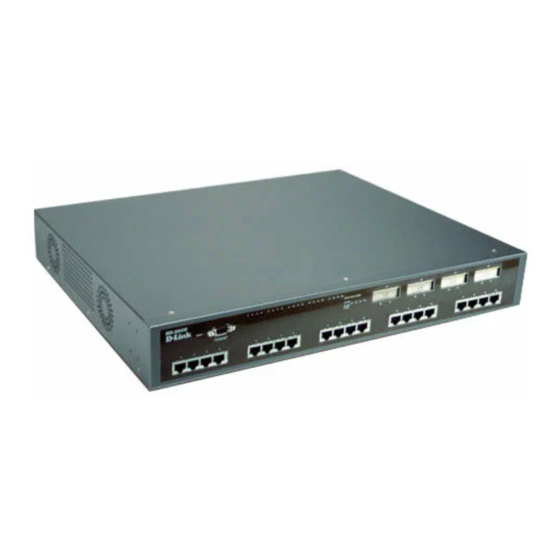
DGS-3224TG Gigabit Ethernet Switch User’s Guide DENTIFYING This chapter describes the front panel, rear panel, side panels, and LED indicators of the DGS-3224TG. Front Panel The front panel of the switch consists of LED indicators, an RS-232 communication port, 20 1000BASE-T ports, and 4 GBIC ports. -
Page 18: Side Panels
Side Panels The right side panel of the switch contains two system fans (see the top part of the diagram below). The left side panel contains heat vents. • The system fans are used to dissipate heat. The sides of the system also provide heat vents to serve the same purpose. -
Page 19: Connecting The Switch
Network Interface Card (NIC) and most routers. An end node can be connected to the switch via a two-pair Category 3, 4, 5, or 5e UTP/STP cable—for optimal performance, Category 5e is recommended. The end node should be connected to any of the ports of the switch. - Page 20 • A 10BASE-T hub or switch can be connected to the switch via a two-pair Category 3, 4, 5, or 5e UTP/STP cable. • A 100BASE-TX hub or switch can be connected to the switch via a two-pair Category 5 or 5e UTP/STP cable.
-
Page 21: Switch Management And Operating Concepts
(see Chapter 6, “Using the Console Interface”). A network administrator can manage, control and monitor the switch from the console program. The DGS-3224TG contains a CPU, memory for data storage, flash memory for configuration data, operational programs, and SNMP agent firmware. These components allow the switch to be actively managed and monitored from either the console port or the network itself (out-of-band, or in-band). -
Page 22: Ip Addresses And Snmp Community Names
100. If you still don’t see anything, try hitting <Ctrl> + r to refresh the screen. IP Addresses and SNMP Community Names Each switch must be assigned its own IP Address, which is used for communication with an SNMP network manager or other TCP/IP application (for example BOOTP, TFTP). The switch’s default IP address is 10.90.90.90. -
Page 23: Traps
For security, you can set in the switch a list of IP Addresses of the network managers that allow you to manage the switch. You can also change the default SNMP Community Strings in the switch and set the access rights of these Community Strings. -
Page 24: Mibs
New Root – This trap indicates that the switch has become the new root of the Spanning Tree, the trap is sent by the switch soon after its election as the new root. This implies that upon expiration of the Topology Change Timer the new root trap is sent out immediately after the switch’s election as the new root. -
Page 25: Authentication
• Modifying the configuration of network devices. The DGS-3224TG has a software program called an ‘agent’ that processes SNMP requests, but the user program that makes the requests and collects the responses runs on a management station (a designated computer on the network). The SNMP agent and the user program both use the UDP/IP protocol to exchange packets. -
Page 26: Spanning Tree Protocol
Each port on the switch is a unique collision domain and the switch filters (discards) packets whose destination lies on the same port as where it originated. This keeps local packets from disrupting communications on other parts of the network. -
Page 27: Bridge Protocol Data Units
STP communicates between switches on the network using Bridge Protocol Data Units (BPDUs). Each BPDU contains the following information: • The unique identifier of the switch that the transmitting switch currently believes is the root switch address. The Bridge Identifier... -
Page 28: Creating A Stable Stp Topology
A designated switch is selected. This is the switch closest to the root switch through which packets will be forwarded to the root. • A port for each switch is selected. This is the port providing the best path from the switch to the root switch. •... - Page 29 • From disabled to blocking When you enable STP, every port on every switch in the network goes through the blocking state and then transitions through the states of listening and learning at power up. If properly configured, each port stabilizes to the forwarding or blocking state.
-
Page 30: User-Changeable Stp Parameters
The user changeable parameters in the Switch are as follows: • Priority – A Priority for the switch can be set from 0 to 65535. 0 is equal to the highest Priority. •... - Page 31 STP will automatically assign root bridges/ports and block loop connections. Influencing STP to choose a particular switch as the root bridge using the Priority setting, or influencing STP to choose a particular port to block using the Port Priority and Port Cost settings is, however, relatively straight forward.
-
Page 32: Vlans
Note also that the example network topology is intended to provide redundancy to protect the network against a link or port failure – not a switch failure or removal. For example, a failure of switch A would isolate LAN 1 from connecting to LAN 2 or LAN 3. -
Page 33: 802.1Q Vlan Packet Forwarding
DGS-3224TG Gigabit Ethernet Switch User’s Guide IEEE 802.1Q (tagged) VLANs are implemented on the DGS-3224TG. 802.1Q VLANs require tagging, which enables them to span the entire network (assuming all switches on the network are IEEE 802.1Q-compliant). VLANs allow a network to be segmented in order to reduce the size of broadcast domains. All packets entering a VLAN will only be forwarded to the stations (over IEEE 802.1Q enabled switches) that are... -
Page 34: 802.1Q Vlan Tags
DGS-3224TG Gigabit Ethernet Switch User’s Guide Figure 5-6. IEEE 802.1Q Packet Forwarding 802.1Q VLAN Tags The figure below shows the 802.1Q VLAN tag. There are four additional octets inserted after the source MAC address. Their presence is indicated by a value of 0x8100 in the EtherType field. When a packet’s EtherType field is equal to 0x8100, the packet carries the IEEE 802.1Q/802.1p tag. -
Page 35: Port Vlan Id
DGS-3224TG Gigabit Ethernet Switch User’s Guide Figure 5-7. IEEE 802.1Q Tag The EtherType and VLAN ID are inserted after the MAC source address, but before the original EtherType/Length or Logical Link Control. Because the packet is now a bit longer than it was originally, the Cyclic Redundancy Check (CRC) must be recalculated. -
Page 36: Tagging And Untagging
Tag-aware switches must keep a table to relate PVIDs within the switch to VIDs on the network. The switch will compare the VID of a packet to be transmitted to the VID of the port that is to transmit the packet. -
Page 37: Dhcp
If the packet is not tagged with VLAN information, the ingress port will tag the packet with its own PVID as a VID. The switch then determines if the destination port is a member of the same VLAN (has the same VID) as the ingress port. - Page 38 DGS-3224TG Gigabit Ethernet Switch User’s Guide...
-
Page 39: Configuring The Switch Using The Console Interface
Notes are added where clarification is necessary. Before You Start The DGS-3224TG supports a wide array of functions and gives great flexibility and increased network performance by eliminating the routing bottleneck between the WAN or Internet and the Intranet. Its function in a network can be thought of as a new generation of router that performs routing functions in hardware, rather than software. -
Page 40: Console Usage Conventions
Note: The passwords used to access the switch are case-sensitive; therefore, “S” is not the same as “s.” When you first connect to the switch, you will be presented with the first login screen (shown below). Note: Press Ctrl+R to refresh the screen. This command can be used at any time to force the console program in the switch to refresh the console screen. - Page 41 DGS-3224TG Gigabit Ethernet Switch User’s Guide Figure 6-1. Initial screen, first time connecting to the switch Note: There is no initial username or password. Leave the Username and Password fields blank. Press Enter in both the Username and Password fields. You will be given access to the main menu shown below: Note: The first user automatically gets Root privileges (See Table 6-1).
-
Page 42: User Accounts Management
DGS-3224TG Gigabit Ethernet Switch User’s Guide User Accounts Management To create a new user account, highlight User Accounts Management from the main menu and press Enter: Figure 6-3. Main menu Figure 6-4. Setup User Accounts screen... - Page 43 After establishing a User Account with Root-level privileges, press Esc. Then highlight Save Changes and press Enter (see below). The Switch will save any changes to its non-volatile ram and reboot. You can logon again and are now ready to continue configuring the Switch.
-
Page 44: Save Changes
DGS-3224TG Gigabit Ethernet Switch User’s Guide Save Changes The DGS-3224TG has two levels of memory; normal RAM and non-volatile or NV-RAM. Configuration changes are made effective by highlighting APPLY and pressing Enter. When this is done, the settings will be immediately applied to the switching software in RAM, and will immediately take effect. -
Page 45: Factory Reset
DGS-3224TG Gigabit Ethernet Switch User’s Guide Figure 6-6. Save changes screen Once the switch configuration settings have been saved to NV-RAM, they become the default settings for the switch. These settings will be used every time the Switch is rebooted. - Page 46 Highlight the appropriate choice and press Enter to reset the switch’s NV-RAM to the factory default settings (or just reboot the switch). Loading the Factory Default Configuration will erase any User Accounts (and all other configuration settings) you may have entered and return the switch to the state it was in when it was...
- Page 47 DGS-3224TG Gigabit Ethernet Switch User’s Guide purchased. The Load Factory Default Configuration Except IP Address option is used when the switch will be managed by the Telnet manager, which requires knowledge of the switch’s IP address to function. Logging Onto The Switch Console To log in once you have created a registered user, from the login screen: 1.
-
Page 48: Viewing Current User Accounts
7. You must enter the configuration changes into the non-volatile ram (NV-RAM) using Save Changes from the main menu if you want the configuration to be used after a switch reboot. Only a user with Root privileges can make changes to user accounts. -
Page 49: Configure Ip Address
Some settings must be entered to allow the switch to be managed from an SNMP-based Network Management System such as SNMP v1 or to be able to access the switch using the Telnet protocol. The Remote Management Setup screen lets you specify how the switch will be assigned an IP address to allow the switch to be identified on the network. - Page 50 BOOTP protocol allows IP addresses, network masks, and default gateways to be assigned by a central BOOTP server. If this option is set, the switch will first look for a BOOTP server to provide it with this information before using the default or previously entered settings.
-
Page 51: Configure Switch Information And Advanced Settings
SLIP and Ethernet network interfaces Subnet Mask – A bitmask that determines the extent of the subnet that the switch is on. Should be of the form xxx.xxx.xxx.xxx, where each xxx is a number (represented in decimal) between 0 and 255. - Page 52 Switch.
-
Page 53: Configure Ports
Trunk Load Sharing Algorithm:<Src Address> – The trunk load sharing options are Dst Address, Src&Dst Address, and Src Address. In addition, clicking REALCLOCK SETTINGS at the bottom of the Configure Advanced Switch Features menu will allow you to configure the Real-time Clock for network monitoring and troubleshooting purposes. -
Page 54: Configure Spanning Tree Protocol
100M/Full, 100M/Half, 10M/Full, 10M/Half. There is no automatic adjustment of port settings with any option other than Auto. Flow Control can be enabled or disabled manually when any setting other than Auto is selected. Please note that the switch’s four GBIC ports only support 1000M/Full. Configure Spanning Tree Protocol... - Page 55 BPDU packets sent by the Root Bridge to tell all other switches that it is indeed the Root Bridge. If you set a Hello Time for your switch, and it is not the Root Bridge, the set Hello Time will be used if and when your switch becomes the Root Bridge.
-
Page 56: Configure Static (Destination-Address Forwarding) Table
Max. Age ≥ 2 x (Hello Time + 1 second) Port Spanning Tree Settings In addition to setting Spanning Tree parameters for use on the switch level, the DGS-3224TG allows for the configuration of Spanning Tree Protocol on individual ports. - Page 57 DGS-3224TG Gigabit Ethernet Switch User’s Guide Figure 6-18. Configure Static (Destination-Address Forwarding) Table menu Setup Unicast Forwarding Table Highlight Configure Static Forwarding Table on the menu above to access the following screen: Figure 6-19. Setup Unicast Forwarding Table screen The Action field can be toggled between Add/Modify and Delete using the space bar. Enter the VID in...
- Page 58 – (Non-Member) – Specifies the port as not being a member of the multicast group, but the port can become a member of the multicast group dynamically. Highlight APPLY and press Enter to make the changes current. Use Save Changes from the main menu to enter the changes into NV-RAM. DGS-3224TG Gigabit Ethernet Switch User’s Guide...
-
Page 59: Configure Vlans
DGS-3224TG Gigabit Ethernet Switch User’s Guide Note: The DGS-3224TG supports a maximum of 16K multicast MAC address entities. Configure VLANs The switch reserves one VLAN, VID = 1, called the DEFAULT_VLAN for internal use. The factory default setting assigns all ports on the switch to the DEFAULT_VLAN. As new VLANs are configured, their respective member ports are removed from the DEFAULT_VLAN. - Page 60 T - specifies the port as a Tagged member of the VLAN. When an untagged packet is transmitted by the port, the packet header is changed to include the 32-bit tag associated Figure 6-22. 802.1Q Static VLAN Settings screen DGS-3224TG Gigabit Ethernet Switch User’s Guide...
- Page 61 DGS-3224TG Gigabit Ethernet Switch User’s Guide with the PVID (Port VLAN Identifier – see below). When a tagged packet exits the port, the packet header is unchanged. If the port is attached to a device that is not IEEE 802.1Q VLAN compliant (VLAN-tag unaware), then the port should be set to U –...
- Page 62 Port GVRP Settings GARP VLAN Registration Protocol (GVRP) is a Generic Attribute Registration Protocol (GARP) application that provides 802.1Q-compliant VLAN pruning and dynamic VLAN creation. With GVRP, the switch can exchange VLAN configuration information with other GVRP switches, prune unnecessary broadcast and unknown unicast traffic, and dynamically create and manage VLANs on switches connected through 802.1Q ports.
-
Page 63: Configure Igmp Snooping
GVRP updates dynamic VLAN registration entries and communicates the new VLAN information across the network. This allows, among other things, for stations to physically move to other switch ports and keep their same VLAN settings, without having to reconfigure VLAN settings on the switch. - Page 64 To configure IGMP Snooping: Toggle the Switch IGMP Snooping field to Enabled. Toggle the Querier State field to the appropriate choice between Non-Querier, V1-Querier, and V2-Querier to determine the version of IGMP that is used in your network. A value between 1 and 255 can be entered for the Robustness Variable (default is 2).
-
Page 65: Configure Trunk
– to the backbone of a network. The switch allows the creation of up to 6 port trunking groups, each group consisting of up to 16 links (ports). The trunked ports can be non-continuous (that is, have non-sequential port numbers). All of the ports in the group must be members of the same VLAN. -
Page 66: Configure Port Mirroring
Switch, STP will block one entire group – in the same way STP will block a single port that has a redundant link. The user-changeable parameters in the switch are as follows: • Group ID:[1] – This field is for a group ID number for the port trunking group. -
Page 67: Configure Class Of Service, Default Priority, And Traffic Class
1–12 or 13–24. Configure Class of Service, Default Priority, and Traffic Class The DGS-3224TG allows you to customize class of service, port default priority, and traffic class settings on the following menu. Select Configure Class of Service, Default Priority and Traffic Class on the Configuration menu and press Enter. - Page 68 Maximum latency takes precedence over the CoS scheduling algorithm. In addition, clicking ADVANCED SETTINGS at the bottom of the Class of Service Configuration menu will enable you to select the desired port queue priority: Figure 6-30. Class of Service Configuration menu DGS-3224TG Gigabit Ethernet Switch User’s Guide...
- Page 69 DGS-3224TG Gigabit Ethernet Switch User’s Guide Figure 6-31. Port Maxlimit Drop Settings screen The Switch divides the buffer into four parts: Queue0, Queue1, Queue2, and Queue3. Queue0 is the highest priority and Queue3 is the lowest. Press APPLY to let the change take effect.
-
Page 70: Traffic Class Configuration
Figure 6-33. Traffic Class Configuration screen This screen allows you to configure traffic class priority by specifying the class value, from 0 to 3, of the switch’s eight levels of priority. Press APPLY to let your changes take effect. Configure RS232 and SLIP... -
Page 71: Network Monitoring
SLIP is selected. Network Monitoring The DGS-3224TG provides extensive network monitoring capabilities. To display the network data compiled by the switch, highlight Network Monitoring on the main menu and press Enter. Figure 6-34. Serial Port and SLIP Settings screen... -
Page 72: Port Utilization
DGS-3224TG Gigabit Ethernet Switch User’s Guide Figure 6-35. Network Monitoring Menu Port Utilization To view the port utilization of all the ports on the switch, highlight Port Utilization on the Network Monitoring Menu and press Enter: Figure 6-36. Port Utilization screen... -
Page 73: Port Error Packets
DGS-3224TG Gigabit Ethernet Switch User’s Guide The Port Utilization screen shows the number of packets transmitted and received per second and calculates the percentage of the total available bandwidth being used on the port (displayed under %Util.). Highlight CLEAR COUNTER and press Enter to reset the counters. -
Page 74: Browse Mac Address
DGS-3224TG Gigabit Ethernet Switch User’s Guide Figure 6-38. Packet Analysis screen In addition to the size of packets received or transmitted by the selected port, statistics on the number of unicast, multicast, and broadcast packets are displayed. Highlight CLEAR COUNTER and press Enter to reset the counters. -
Page 75: Switch History
Enter. Highlight BROWSE and press Enter to initiate the browsing action. Highlight CLEAR ALL and press Enter to reset the table counters. Switch History To view the switch history log, highlight Switch History from the Network Monitoring Menu and press Enter:... -
Page 76: Igmp Snooping
Figure 6-40. Switch History screen IGMP Snooping This allows the switch’s IGMP Snooping table to be viewed. IGMP Snooping allows the switch to read the Multicast Group IP address and the corresponding MAC address from IGMP packets that pass through the switch. The ports where the IGMP packets were snooped are displayed, signified with an M. -
Page 77: Browse Multicast Status
DGS-3224TG Gigabit Ethernet Switch User’s Guide Figure 6-41. IGMP Snooping Status screen Enter a VLAN ID number in the first field and press GO to display the desired IGMP Snooping Status screen. Browse Multicast Status Figure 6-42. Multicast Address Status screen... -
Page 78: Vlan Status
The switch sends out SNMP traps to network management stations whenever certain exceptional events occur, such as when the switch is turned on or when a system reset occurs. The switch allows traps to be routed to up to four different network management hosts. -
Page 79: System Utilities
• IP Address – The IP address of the network management station to receive traps. The Security IP section allows you to create a list of IP addresses that are allowed to access the switch via SNMP or Telnet. Highlight APPLY and press Enter to allow your changes to take effect. -
Page 80: Upgrade Firmware From Tftp Server
TFTP server to the Switch. A configuration file can also be loaded into the Switch from a TFTP server, switch settings can be saved to the TFTP server, and a history log can be uploaded from the Switch to the TFTP server. -
Page 81: Use Configuration File On Tftp Server
Highlight START and press Enter to initiate the file transfer. Use Configuration File on TFTP Server To download a switch configuration file from a TFTP server, highlight Use a Configuration File on TFTP Server and press Enter. Figure 6-46. Upgrade Firmware screen... -
Page 82: Save Settings To Tftp Server
DGS-3224TG Gigabit Ethernet Switch User’s Guide Figure 6-47. Use Configuration File on TFTP Server screen Enter the IP address of the TFTP server and specify the location of the switch configuration file on the TFTP server. Highlight APPLY and press Enter to record the IP address of the TFTP server. Use Save Changes from the main menu to enter the address into NV-RAM Highlight START and press Enter to initiate the file transfer. -
Page 83: Save History Log To Tftp Server
DGS-3224TG Gigabit Ethernet Switch User’s Guide Figure 6-48. Save Settings to TFTP Server screen Enter the IP address of the TFTP server and the path and filename of the settings file on the TFTP server and press APPLY. Highlight START and press Enter to initiate the file transfer. -
Page 84: Ping Test
DGS-3224TG Gigabit Ethernet Switch User’s Guide Figure 6-49. Save Log to TFTP Server screen Enter the IP address of the TFTP server and the path and filename for the history log on the TFTP server. Highlight APPLY and press Enter to make the changes current. Highlight START and press Enter to initiate the file transfer. -
Page 85: Reboot
Enter the IP address of the network device to be Pinged and the number of test packets to be sent (3 is usually enough). Highlight START and press Enter to initiate the Ping program. Reboot The DGS-3224TG has several reboot options. To reboot the switch from the console, highlight Reboot from the main menu and press Enter. - Page 86 The reboot options are as follows: • Reboot – Simply restarts the switch. Any configuration settings not saved using Save Changes from the main menu will be lost. The switch’s configuration will be restored to the last configuration saved in NV-RAM. •...
- Page 87 DGS-3224TG Gigabit Ethernet Switch User’s Guide Figure 6-52. System Reboot confirmation screen To reboot the switch, in the mode entered above, highlight Yes and press Enter.
-
Page 88: Web-Based Network Management
DGS-3224TG Gigabit Ethernet Switch User’s Guide ASED ETWORK ANAGEMENT Introduction The DGS-3224TG offers an embedded Web-based (HTML) interface allowing users to manage the switch from anywhere network through standard browser, such Opera, Netscape Navigator/Communicator, or Microsoft Internet Explorer. The Web browser acts as a universal access tool and can communicate directly with the switch using the HTTP protocol. - Page 89 Click OK as there is no preset user name or password on the switch. This opens the main page in the management module. The top panel shows a real-time front panel display of the DGS-3224TG. Clicking on an individual port on this display will connect you to the Rx Packets Analysis window (see Monitoring→Packets→...
- Page 90 DGS-3224TG Gigabit Ethernet Switch User’s Guide...
- Page 91 DGS-3224TG Gigabit Ethernet Switch User’s Guide These are the major categories for switch management. If the sub-menus for each main category do not appear, click on the small square hyperlink to the left of the folder icon. The switch management features available in the Web-based are explained below.
-
Page 92: Configuration
If you enable DHCP, a Dynamic Host Configuration Protocol request will be sent when the switch is powered up. Once you have selected a setting under Get IP From, click Apply to activate the new settings. -
Page 93: Switch Information
Figure 7-2. Switch Information (Basic Settings) window To set basic switch settings, enter a System Name in the first field, the physical location of the switch in the System Location field, and the name of the contact person responsible for the switch in the System Contact field. -
Page 94: Advanced Settings
The information in the window is described as follows: • Auto-Logout [Never] – This sets the time the interface can be idle before the switch automatically logs-out the user. The options are 2 minutes, 5 minutes, 10 minutes, 15 minutes, or Never. -
Page 95: Port Configuration
1. Enable or disable the port. If you choose Disabled in the State field, devices connected to that port cannot use the switch, and the switch purges their addresses from its address table after the MAC address aging time elapses. -
Page 96: Port Mirroring
4. Click Apply to let your changes take effect. Port Mirroring The switch allows you to copy frames transmitted and received on a port and redirect the copies to another port. You can attach a monitoring device to the mirrored port, such as a sniffer or an RMON probe, to view details about the packets passing through the first port. -
Page 97: Port Trunking
DGS-3224TG Gigabit Ethernet Switch User’s Guide Port Trunking The Switch supports up to 6 trunk groups. Trunks are groups of ports that are banded together to form a single, logical, high-bandwidth data pipe. The maximum number of member ports for a trunk group is To create or modify a trunk group, enter a name in the first field, check the ports that will compose the port trunk, and change the Status field to Enabled. -
Page 98: Spanning Tree
Internet Group Management Protocol (IGMP) snooping allows the switch to recognize IGMP queries and reports sent between network stations or devices and an IGMP host. When enabled for IGMP snooping, the switch can open or close a port to a specific device based on IGMP messages passing through the switch. - Page 99 BPDU packets sent by the Root Bridge to tell all other switches that it is indeed the Root Bridge. If you set a Hello Time for your switch, and it is not the Root Bridge, the set Hello Time will be used if and when your switch becomes the Root Bridge.
-
Page 100: Stp Port Settings
Priority (0~255) – A port priority can be set from 0 to 255. The lower the priority, the greater the probability the port will be chosen as the root port. Figure 7-9. STP Port Settings window DGS-3224TG Gigabit Ethernet Switch User’s Guide... -
Page 101: Static Forwarding Table
DGS-3224TG Gigabit Ethernet Switch User’s Guide Static Forwarding Table Static Unicast Forwarding The window above allows you to set up static packet forwarding on the switch. The information on the window is described as follows: • MAC Address – The MAC address from which packets will be statically filtered. -
Page 102: Vlans
Forbidden to prevent a port from being a member of the VLAN. Click Apply to let the changes take effect. Figure 7-12. 802.1Q Static VLANs window Figure 7-13. 802.1Q Static VLAN Setup window DGS-3224TG Gigabit Ethernet Switch User’s Guide... - Page 103 DGS-3224TG Gigabit Ethernet Switch User’s Guide To modify an entry, click the pointer icon next to the appropriate table entry on the 802.1Q Static VLANs window and then complete the appropriate information on the window above. Click Apply to let your changes take effect.
- Page 104 GARP VLAN Registration Protocol (GVRP) is a Generic Attribute Registration Protocol (GARP) application that provides 802.1Q-compliant VLAN pruning and dynamic VLAN creation on 802.1Q ports. With GVRP, the switch can exchange VLAN configuration information with other GVRP switches, prune unnecessary broadcast and unknown unicast traffic, and dynamically...
-
Page 105: Port Default Priority
DGS-3224TG Gigabit Ethernet Switch User’s Guide create and manage VLANs on switches connected through 802.1Q ports. Click Apply to let your changes take effect. The information on the window is described as follows: • PVID – PVID is used to decide whether received tagged packets belong to a VLAN. -
Page 106: Class Of Traffic
Class of Traffic This window allows you to configure traffic class priority by specifying the class value, from 0 to 3, of the switch’s eight levels of priority. Click Apply to let your changes take effect. Class of Service Figure 7-18. Class of Service Configuration window This window allows you to set the following features: •... - Page 107 DGS-3224TG Gigabit Ethernet Switch User’s Guide can be entered in this field are from 1 to 255. Entering zero instructs the switch to continue processing packets until there are no more packets in the CoS transaction queue. • Max. Latency – The maximum allowable time a packet will stay in the CoS queue, in microseconds and seconds.
-
Page 108: Rs232 & Slip
The switch divides the buffer into four parts: Queue0, Queue1, Queue2, and Queue3. Queue0 is the highest priority and Queue3 is the lowest. Use the window above to select the ports for each of the four queue priorities. Turn the Class State to On for the specified range of ports and then click Apply to let your changes take effect. -
Page 109: Management
This category includes: Security IP, SNMP Manager, Trap Manager, and User Accounts. Security IP Figure 7-21. Security IP Management window Use this window to specify IP addresses that are allowed to access the switch. SNMP Manager Figure 7-22. SNMP Manager Configuration window To use the functions on this window, enter the appropriate SNMP information. -
Page 110: Trap Manager
Status – Option to set the trap receiving station to Valid or Invalid. User Accounts The Switch allows you to set up and manage user accounts in the following two windows. User Account Management The information on the window is described as follows: •... -
Page 111: Monitoring
(TX)), Errors (Received (RX) and Transmitted (TX)), Size (Received (RX)), MAC Address Table, IGMP Snooping Table, VLAN Multicast Table, IGMP Multicast Table, and VLAN Status Table, and secondary windows. Port Utilization The Switch can display the utilization percentage of a specified port in the window below. Figure 7-25. User Account Modify Table window... -
Page 112: Packets
Time Interval – Select the desired setting between 1s and 60s, where “s” stands for seconds. The default value is one second. • Record Number – Select number of times the switch will be polled between 20 and 200. The default value is 20. •... - Page 113 DGS-3224TG Gigabit Ethernet Switch User’s Guide Received (RX) Figure 7-27. Rx Packets Analysis window (Line Chart)
- Page 114 View Table – Clicking this button instructs the switch to display a table rather than a line graph. • View Line Chart – Clicking this button instructs the switch to display a line graph rather than a table. Figure 7-28. Rx Packets Analysis window (Table)
- Page 115 DGS-3224TG Gigabit Ethernet Switch User’s Guide UMB-cast (RX) Figure 7-29. Rx Packets Analysis window for UMB_cast (Line Chart)
- Page 116 View Table – Clicking this button instructs the switch to display a table rather than a line graph. • View Line Chart – Clicking this button instructs the switch to display a line graph rather than a table. DGS-3224TG Gigabit Ethernet Switch User’s Guide...
-
Page 117: Transmitted (Tx)
DGS-3224TG Gigabit Ethernet Switch User’s Guide Transmitted (TX) Figure 7-31. Tx Packets Analysis window (Line Chart) -
Page 118: Errors
View Table – Clicking this button instructs the switch to display a table rather than a line graph. • View Line Chart – Clicking this button instructs the switch to display a line graph rather than a table. Errors The Web Manager allows port error statistics compiled by the switch’s management agent to be viewed as either a line graph or a table. - Page 119 DGS-3224TG Gigabit Ethernet Switch User’s Guide Received (RX) Figure 7-33. Rx Error Analysis window (Line Chart) Figure 7-34. Rx Error Analysis window (Table) The information is described as follows:...
- Page 120 View Table – Clicking this button instructs the switch to display a table rather than a line graph. • View Line Chart – Clicking this button instructs the switch to display a line graph rather than a table. DGS-3224TG Gigabit Ethernet Switch User’s Guide...
- Page 121 DGS-3224TG Gigabit Ethernet Switch User’s Guide Transmitted (TX) Figure 7-35. Tx Error Analysis window (Line Chart)
- Page 122 View Table – Clicking this button instructs the switch to display a table rather than a line graph. • View Line Chart – Clicking this button instructs the switch to display a line graph rather than a table. Figure 7-36. Packet Analysis window (Table)
-
Page 123: Size
DGS-3224TG Gigabit Ethernet Switch User’s Guide Size The Web Manager allows packets transmitted and received by the switch, arranged in six groups, to be viewed as either a line graph or a table. The two windows offered are as follows: Packet Size Figure 7-37. - Page 124 Time Interval – Select the desired setting between 1s and 60s, where “s” stands for seconds. The default value is one second. • Record Number – Select number of times the switch will be polled between 20 and 200. The default value is 20. •...
-
Page 125: Mac Address Table
View Table – Clicking this button instructs the switch to display a table rather than a line graph. • View Line Chart – Clicking this button instructs the switch to display a line graph rather than a table. MAC Address Table The Web Manager allows the switch’s MAC address table (sometimes referred to as a forwarding table) -
Page 126: Igmp Snooping Table
Next – Click this button to view the next page of the address table. IGMP Snooping Table The switch’s IGMP snooping table can be browsed using the Web Manager. The table is displayed by VLAN ID (VID). The information is described as follows: •... -
Page 127: Vlan Multicast Table
• Status – This indicates the current status of the VID listed above. • Creation time since switch power up – The hours, minutes, and seconds since the switch was last rebooted. Figure 7-41. VLAN Multicast Table window Figure 7-42. IGMP Multicast Table window... -
Page 128: Maintenance
File Name – The full file name (including path) of the new firmware file on the TFTP server. Configuration File A configuration file can be downloaded from a TFTP server to the switch. This file is then used by the switch to configure itself. -
Page 129: Save Settings
Save History Log The switch’s management agent can upload its history log file to a TFTP server. Please note that an empty history file on the TFTP server must exist on the server before the switch can upload its history file. -
Page 130: Switch History
Enter the IP address of the TFTP Server in the Server IP Address field and the complete path and file name of the firmware file for the switch. Click Apply to enter the server’s IP address into the switch’s RAM (use Save Changes to enter the address into the switch’s non-volatile RAM). Click Start to initiate the file transfer. -
Page 131: Ping Test
Trap Logs. The information is described as follows: • Sequence – A counter incremented whenever an entry to the switch’s history log is made. The table displays the last entry (highest sequence number) first. •... -
Page 132: Save Changes
(3 is usually enough). Click Start to initiate the Ping program. Save Changes Figure 7-50. Save Configuration window To save all the changes made in the current session to the switch’s flash memory, click the Save Configuration button. -
Page 133: Factory Reset
DGS-3224TG Gigabit Ethernet Switch User’s Guide Factory Reset Figure 7-51. Factory Reset to Default Value window A remote reset returns the switch to the initial parameters set at the factory. Click Reset to Factory Default to reset the switch. Restart System Figure 7-52. -
Page 134: Connection Timeout
DGS-3224TG Gigabit Ethernet Switch User’s Guide Connection Timeout Figure 7-53. Web Timeout Setup window To use this Web timeout feature, enter the desired age-out time and then click Apply. Logout Figure 7-54. Logout Web Setups window To exit the setup pages and return to the main page, click Apply. -
Page 135: Technical Specifications
DGS-3224TG Gigabit Ethernet Switch User’s Guide Standards: Protocols: Data Transfer Rates: Ethernet: Fast Ethernet: Gigabit Ethernet: Topology: Network Cables 10BASE-T: 100BASE-TX: 1000BASE-T: GBIC: ECHNICAL General IEEE 802.3 10BASE-T Ethernet IEEE 802.3u 100BASE-TX Fast Ethernet IEEE 802.3z Gigabit Ethernet IEEE 802.1Q Tagged VLAN IEEE 802.1P Tagged Packets... -
Page 136: Physical And Environmental
(for 100Mbps) 1,488,100 pps per port (for 1000Mbps) MAC Address Automatic update. Supports 32K Learning: MAC address. Priority Queues: 4 Priority Queues per port. Forwarding Table Max age: 17–2100 seconds. Age Time: Default = 300. DGS-3224TG Gigabit Ethernet Switch User’s Guide... - Page 137 DGS-3224TG Gigabit Ethernet Switch User’s Guide...
-
Page 138: Cable Lengths
9µm Single-mode Fiber Category 5e UTP Cable Category 5 UTP Cable (1000 Mbps) Category 5 UTP Cable (100 Mbps) Category 3 UTP Cable (10 Mbps) DGS-3224TG Gigabit Ethernet Switch User’s Guide ABLE ENGTHS Maximum Distance 550 Meters 550 Meters 5,000 Meters... -
Page 139: Runtime Switching Software Default Settings
DGS-3224TG Gigabit Ethernet Switch User’s Guide UNTIME Load mode Configuration update Firmware update Out-of-band baud rate RS232 mode IP address Subnet mask Default gateway BootP service TFTP server IP address Auto log-out User name Password MAC address aging time IGMP snooping... -
Page 140: Understanding And Troubleshooting The Spanning Tree Protocol
BPDUs with other switches. This will determine which switch in the network is the best choice for the root switch. If there is only one switch on the network, no BPDU exchange occurs, the forward delay timer expires, and the ports move to the listening state. All STP enabled ports enter the blocking state following switch boot. -
Page 141: Listening State
The listening state is the first transition for a port from the blocking state. Listening is an opportunity for the switch to receive BPDUs that may tell the switch that the port should not continue to transition to the forwarding state, but should return to the blocking state (that is, a different port is a better choice). -
Page 142: Learning State
Discards packets sent from another port on the switch for forwarding. • Adds addresses to its forwarding database. • Receives BPDUs and directs them to the CPU. • Processes and transmits BPDUs received from the CPU. • Receives and responds to network management messages. DGS-3224TG Gigabit Ethernet Switch User’s Guide... -
Page 143: Forwarding State
DGS-3224TG Gigabit Ethernet Switch User’s Guide Forwarding State A port in the forwarding state forwards packets. The port enters the forwarding state from the learning state when the forward delay timer expires. A port in the forwarding state does the following: •... -
Page 144: Disabled State
Does not add addresses to its forwarding database. • Receives BPDUs, but does not direct them to the system CPU. • Does not receive BPDUs for transmission from the system CPU. • Receives and responds to network management messages. DGS-3224TG Gigabit Ethernet Switch User’s Guide... -
Page 145: Troubleshooting Stp
DGS-3224TG Gigabit Ethernet Switch User’s Guide Troubleshooting STP Spanning Tree Protocol Failure A failure in the STA generally leads to a bridging loop. A bridging loop in an STP environment comes from a port that should be in the blocking state, but is forwarding packets. -
Page 146: Full/Half Duplex Mismatch
DGS-3224TG Gigabit Ethernet Switch User’s Guide In this example, B has been elected as the designated bridge and port 2 on C is in the blocking state. The election of B as the designated bridge is determined by the exchange of BPDUs between B and C. B had a better BPDU than C. -
Page 147: Unidirectional Link
DGS-3224TG Gigabit Ethernet Switch User’s Guide In the above example, port 1 on B is configured as a full-duplex port and port 1 on A is either configured as a half-duplex port, or left in auto-negotiation mode. Because port 1 on B is configured as a full-duplex port, it does not do the carrier sense when accessing the link. -
Page 148: Packet Corruption
Resource Errors The DGS-3224TG performs its switching and routing functions primarily in hardware, using specialized ASICs. STP is implemented in software and is thus reliant upon the speed of the CPU and other factors to converge. If the CPU is over-utilized, it is possible that BPDUs may not be sent in a timely fashion. - Page 149 Although the STP can elect a root bridge, a well-designed network will have an identifiable root for each VLAN. Careful setup of the STP parameters will lead to the selection of this best switch as the root for each VLAN. Redundant links can then be built into the network. STP is well suited to maintaining connectivity in the event of a device failure or removal, but is poorly suited to designing networks.
- Page 150 DGS-3224TG Gigabit Ethernet Switch User’s Guide In this example, the VLAN definitions are extended to switches A and B. This gives only a single blocked port per VLAN and allows the removal of all redundant links by removing switch A or B from the network.
-
Page 151: Brief Review Of Bitwise Logical Operations
DGS-3224TG Gigabit Ethernet Switch User’s Guide RIEF EVIEW OF The logical operation compares 2 bits and if they are both “ otherwise, the result is “0”. The logical operation compares 2 bits and if either or both bits are otherwise, the result is “0”. -
Page 152: Index
Data forwarding ... 2 Default Gateway ... 40 Diagnostic port... 2 Dimensions... 125 Dynamic filtering ... 16 Egress port ... 22 DGS-3224TG Gigabit Ethernet Switch User’s Guide End Node ...9 factory reset ...34 Filtering...15 Flash memory ...3 Forwarding...15 Front Panel...7 gateway router ...13... - Page 153 DGS-3224TG Gigabit Ethernet Switch User’s Guide password ... 30 Port Mirroring ... 55 Port Priority... 20, 45 ports... 2 Power ... 8 Power Consumption... 125 RAM ... 33 RAM Buffer ... 125 Rear Panel ... 7, 8 refresh ... 29 RMON probe ...
- Page 154 E-MAIL: service@dlink.india.com Italy D-Link Mediterraneo Srl/D-Link Italia Via Nino Bonnet n. 6/b, 20154, Milano, Italy TEL: 39-02-2900-0676 FAX: 39-02-2900-1723 URL: www.dlink.it E-MAIL: info@dlink.it Japan D-Link Japan 10F, 8-8-15 Nishi-Gotanda, Shinagawa-ku, Tokyo 141, Japan TEL: 81-3-5434-9678 FAX: 81-3-5434-9868 URL: www.d-link.co.jp E-MAIL: kida@d-link.co.jp...
- Page 155 South Africa D-Link South Africa 102 – 106 Witchhazel Avenue, Einstein Park 2, Block B, Highveld Technopark, Centurion, South Africa TEL: 27 (0) 12-665-2165 FAX: 27 (0) 12-665-2186 URL: www.d-link.co.za E-MAIL: attie@d-link.co.za Spain D-Link Iberia C/Sabino De Arana, 56 Bajos, 08028 Barcelona, Spain TEL: 34 93 4090770 FAX: 34 93 4910795 URL: www.dlinkiberia.es...
Need help?
Do you have a question about the DGS-3224TG and is the answer not in the manual?
Questions and answers