Table of Contents
Advertisement
Quick Links
[
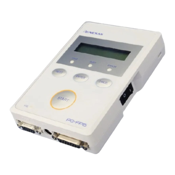
PG-FP6, Renesas Flash Programmer
Additional Document for User's Manual
(Recommended Circuits for Connecting
the Flash Programmer)
All information contained in these materials, including products and product specifications,
represents information on the product at the time of publication and is subject to change by
Renesas Electronics Corp. without notice. Please review the latest information published by
Renesas Electronics Corp. through various means, including the Renesas Electronics Corp.
website (http://www.renesas.com).
Rev. 1.00 Oct 2022
www.renesas.com
Advertisement
Table of Contents

Related Manuals for Renesas PG-FP6


Summary of Contents for Renesas PG-FP6
- Page 1 All information contained in these materials, including products and product specifications, represents information on the product at the time of publication and is subject to change by Renesas Electronics Corp. without notice. Please review the latest information published by Renesas Electronics Corp. through various means, including the Renesas Electronics Corp.
- Page 2 Renesas Electronics disclaims any and all liability for any damages or losses incurred by you or any third parties arising from the use of any Renesas Electronics product that is inconsistent with any Renesas Electronics data sheet, user’s manual or other Renesas Electronics document.
- Page 3 Unit Products The following usage notes are applicable to all Microprocessing unit and Microcontroller unit products from Renesas. For detailed usage notes on the products covered by this document, refer to the relevant sections of the document as well as any technical updates that have been issued for the products.
- Page 4 Renesas Electronics microcontroller equipped with on-chip flash memory. The homepages for the following products have links to the documents for the PG-FP6 and Renesas Flash Programmer. Use the latest versions of the documents.
- Page 5 COMx as the tool to be used. Any value from 1 to 256 can be specified for x. Abbreviation of “microcontroller unit” Target device The Renesas Electronics MCU with on-chip flash memory which is in use by the user Target system User-designed board on which the target device is mounted...
-
Page 6: Table Of Contents
Table of Contents 1. Overview ..........................7 Overview of the PG-FP6 and Renesas Flash Programmer ............... 7 Configuration of Manuals ........................... 7 2. Designing a Target System ....................8 Connection with the Target System ......................8 Connection with the Target System by Using a COM Port ................ 8 Supported Microcontrollers ........................ -
Page 7: Overview
The PG-FP6 (hereafter referred to as the FP6) and Renesas Flash Programmer (hereafter referred to as the RFP) are tools that are used to erase, write, and verify programs on a target system on which a Renesas Electronics single-chip MCU with on-chip flash memory is mounted. -
Page 8: Designing A Target System
COM port of the host machine. For details on the connection, refer to section 4.2, Examples of Recommended Connections with the Use of a COM Port. Refer to List of MCUs supported by Renesas Flash Programmer V3 to confirm whether the target device supports COM port connection. -
Page 9: Pin Configurations Of The Target Cables
PG-FP6, Renesas Flash Programmer 2. Designing a Target System Pin Configurations of the Target Cables The following lists the pin configurations of the target cables for the emulators (E1, E20, E2, or E2 Lite) used with the FP6 and RFP. -
Page 10: Target Cable (20-Pin Conversion Adapter) For The Fp6
PG-FP6, Renesas Flash Programmer 2. Designing a Target System 2.4.2 Target Cable (20-pin Conversion Adapter) for the FP6 When the CoreSight 20-pin connector is used on the target system, use the 20-pin conversion adapter for the FP6. When the 10-pin connector is used on the target system, use the 20-pin to 10-pin conversion cable to match it. -
Page 11: Target Cables (14-Pin And 38-Pin Types) For Emulators For The Rfp
PG-FP6, Renesas Flash Programmer 2. Designing a Target System 2.4.3 Target Cables (14-pin and 38-pin Types) for Emulators for the RFP Table 2-3 Pin Configurations of the 14-pin and 38-pin Connectors for the E1, E20, E2, and E2 Lite Signal Name (RX Family)*... -
Page 12: Target Cable (20-Pin Type) For Emulators For The Rfp
PG-FP6, Renesas Flash Programmer 2. Designing a Target System 2.4.4 Target Cable (20-pin Type) for Emulators for the RFP Table 2-4 Pin Configuration of the CoreSight 20-pin Connector for the E2 and E2 Lite Signal Name (RA Family)* Signal Name (RE Family)*... -
Page 13: Connections With Microcontrollers (Fp6)
PG-FP6, Renesas Flash Programmer 3. Connections with Microcontrollers (FP6) Connections with Microcontrollers (FP6) This chapter describes the connections of the FP6 with microcontrollers. Refer to the recommended design for the connection of pins for the MCU. The pin names might differ depending on the target device. For details about the actual pin names, refer to the user’s manual of each target device. -
Page 14: Rl78 (Single-Wire Uart Communications, Vdd = Evdd)
PG-FP6, Renesas Flash Programmer 3. Connections with Microcontrollers (FP6) RL78 (Single-wire UART Communications, VDD = EVDD) Note: These pins do not need to be short-circuited unless the FP6 is used with the E1, E20, E2, or E2 Lite. Figure 3.2... -
Page 15: Rl78 (Single-Wire Uart Communications, Vdd ≠ Evdd)
PG-FP6, Renesas Flash Programmer 3. Connections with Microcontrollers (FP6) RL78 (Single-wire UART Communications, VDD ≠ EVDD) Notes: 1. These pins do not need to be short-circuited unless the FP6 is used with the E1, E20, E2, or E2 Lite. 2. To perform when VDD ≠ EVDD, connect the conversion adaptor FL-RL78/FP5 (a product of Naito Densei Machida Mfg. -
Page 16: Rx And Superh (Sci Communications)
PG-FP6, Renesas Flash Programmer 3. Connections with Microcontrollers (FP6) RX and SuperH (SCI Communications) Notes: 1. These pins do not need to be short-circuited unless the FP6 is used with the E1, E20, E2, or E2 Lite. 2. Connect the mode setting pins of operating mode to any of the IO0 to IO5 pins. The signal settings for IO0 to IO5 pins can be set in the [Mode Pins Setting] dialog box on the [Connect Setting] tab in the [Setup] dialog box. -
Page 17: Rx (Fine Communications)
PG-FP6, Renesas Flash Programmer 3. Connections with Microcontrollers (FP6) RX (FINE Communications) Notes: 1. These pins do not need to be short-circuited unless the FP6 is used with the E1, E20, E2, or E2 Lite. 2. The UB pin controls entry to the user boot mode. Set up the UB pin to select the boot mode (SCI) or connect the pin to IO2 of the target connector. -
Page 18: Rh850 Type 1 (1-Wire Uart Communications)
PG-FP6, Renesas Flash Programmer 3. Connections with Microcontrollers (FP6) RH850 Type 1 (1-wire UART Communications) Notes: 1. These pins do not need to be short-circuited unless the FP6 is used with the E1, E20, or E2. 2. In case of using the alternate-function pin with a pull-up resistor, connect the pin to IO1 of the target connector. -
Page 19: Rh850 Type 1 (2-Wire Uart Or Csi Communications)
PG-FP6, Renesas Flash Programmer 3. Connections with Microcontrollers (FP6) RH850 Type 1 (2-wire UART or CSI Communications) Notes: 1. These pins do not need to be short-circuited unless the FP6 is used with the E1, E20, or E2. 2. In case of using the alternate-function pin with a pull-up resistor, connect the pin to IO1 of the target connector. -
Page 20: Rh850 Type 2 (2-Wire Uart Or Csi Communications)
PG-FP6, Renesas Flash Programmer 3. Connections with Microcontrollers (FP6) RH850 Type 2 (2-wire UART or CSI Communications) Notes: 1. These pins do not need to be short-circuited unless the FP6 is used with the E1, E20, or E2. 2. These pins do not need to be short-circuited when using 2-wire UART. -
Page 21: Renesas Synergy (Uart Communications)
PG-FP6, Renesas Flash Programmer 3. Connections with Microcontrollers (FP6) Renesas Synergy (UART Communications) Notes: 1. The value of each resistor should be in the range from 4.7 KΩ to 10 KΩ. 2. The need for the clock circuit might differ depending on the target device. Refer to the user’s manual of the target device. -
Page 22: Re (Uart Communications)
PG-FP6, Renesas Flash Programmer 3. Connections with Microcontrollers (FP6) 3.10 RE (UART Communications) The following shows the conversion of each signal when a 14-pin target cable and 20-pin conversion adapter are connected to the 15-pin D-sub connector of the FP6. -
Page 23: And V850 (Uart Communications)
PG-FP6, Renesas Flash Programmer 3. Connections with Microcontrollers (FP6) 3.11 78K and V850 (UART Communications) Notes: 1. These pins do not need to be short-circuited unless the FP6 is used with the E1 or E20. 2. In case of using the alternate-function pin with a pull-up resistor, connect the pin to FLMD1 of the target connector. -
Page 24: And V850 (Csi Communications)
PG-FP6, Renesas Flash Programmer 3. Connections with Microcontrollers (FP6) 3.12 78K and V850 (CSI Communications) Notes: 1. These pins do not need to be short-circuited unless the FP6 is used with the E1 or E20. 2. In case of using the alternate-function pin with a pull-up resistor, connect the pin to FLMD1 of the target connector. -
Page 25: And V850 (Csi-H/S Communications)
PG-FP6, Renesas Flash Programmer 3. Connections with Microcontrollers (FP6) 3.13 78K and V850 (CSI-H/S Communications) Notes: 1. These pins do not need to be short-circuited unless the FP6 is used with the E1 or E20. 2. In case of using the alternate-function pin with a pull-up resistor, connect the pin to FLMD1 of the target connector. -
Page 26: 78K0S (Single-Wire Uart Communications)
PG-FP6, Renesas Flash Programmer 3. Connections with Microcontrollers (FP6) 3.14 78K0S (Single-wire UART Communications) Note: These pins do not need to be short-circuited when using the FP6. Short-circuit them if necessary. Figure 3.14 Example of a Circuit for 78K0S (Single-wire UART) R20UT5195EJ0100 Rev.1.00... -
Page 27: 78K0R (Single-Wire Uart Communications)
PG-FP6, Renesas Flash Programmer 3. Connections with Microcontrollers (FP6) 3.15 78K0R (Single-wire UART Communications) Note: These pins do not need to be short-circuited when using the FP6. Short-circuit them if necessary. Figure 3.15 Example of a Circuit for 78K0R (Single-wire UART) R20UT5195EJ0100 Rev.1.00... -
Page 28: 78K0 (Toolcx And Tooldx Communications)
PG-FP6, Renesas Flash Programmer 3. Connections with Microcontrollers (FP6) 3.16 78K0 (TOOLCx and TOOLDx Communications) Note: These pins do not need to be short-circuited when using the FP6. Short-circuit them if necessary. Figure 3.16 Example of a Circuit for 78K0 (TOOLCx and TOOLDx) R20UT5195EJ0100 Rev.1.00... -
Page 29: V850E2 (Single-Wire Uart Communications)
PG-FP6, Renesas Flash Programmer 3. Connections with Microcontrollers (FP6) 3.17 V850E2 (Single-wire UART Communications) Notes: 1. These pins do not need to be short-circuited when using the FP6. Short-circuit them if necessary. 2. In case of using the alternate-function pin with a pull-up resistor, connect the pin to FLMD1 of the target connector. -
Page 30: V850E2 (Csi Communications)
PG-FP6, Renesas Flash Programmer 3. Connections with Microcontrollers (FP6) 3.18 V850E2 (CSI Communications) Notes: 1. These pins do not need to be short-circuited when using the FP6. Short-circuit them if necessary. 2. In case of using the alternate-function pin with a pull-up resistor, connect the pin to FLMD1 of the target connector. -
Page 31: R8C
PG-FP6, Renesas Flash Programmer 3. Connections with Microcontrollers (FP6) 3.19 Note: These pins do not need to be short-circuited unless the FP6 is used with the E1, E20, or E8a. Figure 3.19 Example of a Circuit for R8C Family R20UT5195EJ0100 Rev.1.00... -
Page 32: Optional Products For The Fp6
PG-FP6, Renesas Flash Programmer 3. Connections with Microcontrollers (FP6) 3.20 Optional Products for the FP6 We provide useful optional products (separately sold) for use with the FP6. 14-pin to 16-pin conversion adapter for the E1 emulator (type name: QB-F14T16-01) •... -
Page 33: Connections With Microcontrollers (Rfp)
For the corresponding names and types of MCUs, refer to List of MCUs Supported by Renesas Flash Programmer V3, which is on the Web site. For the names and handling of pins used for writing, refer to the user’s manual of the MCU. -
Page 34: Example Of A Circuit Of Type A (2-Wire Uart)
PG-FP6, Renesas Flash Programmer 4. Connections with Microcontrollers (RFP) 4.2.1 Example of a Circuit of Type A (2-wire UART) Notes: 1. The value of the resistor is assumed to be 4.7 KΩ. However, specify appropriate values for the pull-up and pull- down resistors in consideration of the electrical characteristics of the particular MCU. -
Page 35: Example Of A Circuit Of Type B (1-Wire Uart)
PG-FP6, Renesas Flash Programmer 4. Connections with Microcontrollers (RFP) 4.2.2 Example of a Circuit of Type B (1-wire UART) Notes: 1. The value of the resistor is assumed to be 4.7 KΩ. However, specify appropriate values for the pull-up and pull- down resistors in consideration of the electrical characteristics of the particular MCU. -
Page 36: Example Of A Circuit Of Type C (2-Wire Uart)
PG-FP6, Renesas Flash Programmer 4. Connections with Microcontrollers (RFP) 4.2.3 Example of a Circuit of Type C (2-wire UART) This example is on the assumption that the circuit is for an RX62T-group MCU. Notes: 1. The value of the resistor is assumed to be 4.7 KΩ. However, specify appropriate values for the pull-up and pull- down resistors in consideration of the electrical characteristics of the particular MCU. -
Page 37: Settings For Reset Signals For The Rfp
PG-FP6, Renesas Flash Programmer 4. Connections with Microcontrollers (RFP) Settings for Reset Signals for the RFP For the reset pins shown in the examples of circuits in section 4.2, Examples of Recommended Connections with the Use of a COM Port, since the reset signals can be set in the software for the RFP, a circuit using an inverter without applying a reset through the RTS signal can be used. -
Page 38: Points For Caution
PG-FP6, Renesas Flash Programmer 4. Connections with Microcontrollers (RFP) Points for Caution Compatibility with the host PC or the USB-to-serial converter • We do not recommend the use of a USB-to-serial converter because it may cause delays in timing and data being lost due to the specifications of the converter. - Page 39 PG-FP6, Renesas Flash Programmer Revision History Additional Document for User’s Manual (Recommended Circuits for Connecting the Flash Programmer) Rev. Date Description Page Summary 1.00 Oct.01.22 First Edition issued ...
- Page 40 PG-FP6, Renesas Flash Programmer Additional Document for User’s Manual (Recommended Circuits for Connecting the Flash Programmer) Publication Date: Rev.1.00 Oct.01.22 Published by: Renesas Electronics Corporation...
- Page 41 PG-FP6, Renesas Flash Programmer Additional Document for User’s Manual (Recommended Circuits for Connecting the Flash Programmer) R20UT5195EJ0100...
Need help?
Do you have a question about the PG-FP6 and is the answer not in the manual?
Questions and answers