
Related Manuals for Elba EX 1266 M


Summary of Contents for Elba EX 1266 M
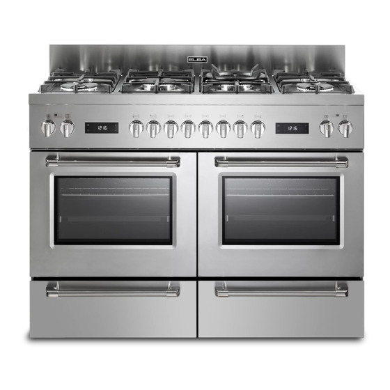
- Page 1 Instructions for the use - Installation advices DUAL FUEL COOKERS ELBA QUALITY MADE IN ITALY Made in Italy...
-
Page 2: Declaration Of Ce Conformity
Dear Customer, Thank you for having purchased and given your preference to our product. The safety precautions and recommendations within this booklet are for your own safety and that of others. They will also provide a means by which to make full use of the features offered by your appliance. -
Page 3: Important Safety Precautions And Recommendations
IMPORTANT SAFETY PRECAUTIONS AND RECOMMENDATIONS IMPORTANT: This appliance is designed and manufactured solely for the cooking of domestic (household) food and is not suitable for any non domestic application and therefore should not be used in a commercial environment. The appliance guarantee will be void if the appliance is used within a non domestic environment i.e. - Page 4 • Do not attempt to modify the technical characteristics of the appliance as this may become dangerous to use. The manufacturer declines all responsibility for any inconvenience resulting from the inobservance of this condition. • CAUTION: this appIiance must only be installed in a permanently ventilated room in compliance with the applicable regulations.
- Page 5 Children shall not play with the appliance. Cleaning and user maintenance shall not be made by children without supervision. • The manufacturer declines all liability for injury to persons or damage to property caused by incorrect or improper use of the appliance.
- Page 6 • CAUTION: Do not use harsh abrasive cleaners or sharp metal scrapers to clean the oven door glass since they can scratch the surface, which may result in shattering of the glass. • Do not line the oven walls or base with aluminium foil. Do not place baking trays or the drip tray on the base of the oven chamber.
- Page 7 • If the power supply cable is damaged, it must be replaced only by an authorized service agent in order to avoid a hazard. • If the appliance is not fitted with a supply cord and a plug, or with other means for disconnection from the supply mains having a contact separation in all poles that provide full disconnection under...
- Page 8 ENERGY LABELLING/ECODESIGN • Commission delegated regulation (EU) No 65/2014 (supplementing Directive 2010/30/EU of the European Parliament and of the Council). • Commission regulation (EU) No 66/2014 (implementing Directive 2009/125/EC of the European Parliament and of the Council). Reference to the measurement and calculation methods used to establish compliance with the above requirements: •...
- Page 9 Advice for the Advice for the installer installer IMPORTANT: • The appliance is designed and approved for domestic use only and should not be installed in a commercial, semi commercial or communal environment. Your product will not be guaranteed if installed in any of the above environments and could affect any third party or public liability insurances you may have.
-
Page 10: Installation
INSTALLATION The installation conditions, concerning protection against overheating of the surfaces adjacent to the cooker, must conform to figs. 1.1a or 1.1b. The appliance must be kept no less than 200 mm away from any side wall which exceeds the height of the hob surface (figs. 1.1a or 1.1b). veneered synthetical material and the glue used must... - Page 11 Before installing the cooker level the appliance by screwing or unscrewing the six adjustable feet fitted below. WARNING! For safety reasons unscrew the feet (from screwed position) to the maximum extent of 10 mm (fig. 1.2). + 10 mm Fig. 1.2 BACKGUARD •...
-
Page 12: Moving The Cooker
MOVING THE COOKER WARNING: When raising cooker to upright position always ensure two people carry out this manoeuvre to prevent damage to the adjustable feet (fig. 1.4). Fig. 1.4 WARNING WARNING Be careful: do not lift the cooker by the When moving cooker to its final position door handle when raising to the upright DO NOT DRAG (fig. -
Page 13: Anti-Tilt Bracket
ANTI-TILT BRACKET Warning: This appliance must be restrained to prevent accidental tipping by fitting a bracket to the rear of the appliance and securely fixing it to the wall. To fit the anti-tilt bracket: After you have located where the cooker is to be positioned, mark on the wall and on the floor the place where the four screws of the anti-tilt bracket have to be fitted. -
Page 14: Ventilation Requirements
VENTILATION REQUIREMENTS The appliance must be installed in compliance with applicable local regulations concerning ventilation and the evacuation of exhaust gases. Intensive and prolonged use may require extra ventilation, e.g. opening a window, or more efficient ventilation increasing the mechanical suction power if this is fitted. CHOOSING SUITABLE SURROUNDINGS The room where the gas appliance is to be installed must have a natural flow of air so that the gas can burn (in compliance with applicable local regulations). -
Page 15: Gas Section
GAS SECTION GAS INSTALLATION REQUIREMENTS Important! • This appliance must be installed and serviced only by a suitably qualified, registered installer. The installer shall refer to the local standards in force. Failure to install the appliance correctly could invalidate any manufacturer’s •... -
Page 16: Connecting The Appliance To The Gas Supply
CONNECTING THE APPLIANCE TO THE GAS SUPPLY The gas connection must be carried out by an authorised person according to the relevant standards. Ensure that the room in which the cooker is to be installed is adequately ventilated, in compliance with applicable regulations. •... - Page 17 POSSIBLE GAS CONNECTIONS GAS CONNECTION WITH A RUBBER HOSE Important! A rubber hose connection shall only be made if permitted by the applicable local regulations. The gas connection is made up of: • the terminal fitting of the inlet pipe; •...
- Page 18 • the hose is replaced at the printed due date or if it shows signs of wear or damage, and replaced regardless of its condition after a maximum of three years. • you inform the customer that the gas cylinder valve or the gas supply valve immediately by the cooker should be closed when the cooker is not in use.
- Page 19 GAS CONNECTION WITH RIGID PIPES OR A FLEXIBLE PIPE The gas connection is made up of: • the terminal fitting of the inlet pipe; • sealing washer. Important! If fitted, remove the hose holder from the terminal fitting of the inlet pipe. When connecting the cooker to the gas supply with rigid pipes or a flexible pipe, make sure that •...
- Page 20 Gas connection with rigid or flexible pipe Note: if already fitted on the inlet pipe, remove the rubber hose holder Inlet pipe Manifold This figure is male pipe fitting indicative only. 1/2” G cylindrical (ISO 228-1) male Sealing ISO 228-1 (female) IMPORTANT! 1/2”...
-
Page 21: Lubrication Of The Gas Taps
TABLE FOR THE CHOICE OF THE INJECTORS G30/G31 Cat: II 2H 3+ 28-30/37 mbar 20 mbar G30/G31 G20/G25 Cat: II 2E +3+ 28-30/37 mbar 20/25 mbar Reduced Nominal Ø injector Ø injector BURNERS power power [kW] [1/100 mm] [1/100 mm] [kW] Semi-rapid (SR) 1,75... -
Page 22: Adjusting Of The Minimum Of The Top Burners
REPLACEMENT OF THE INJECTORS Semi-rapid Fig. 2.4 If the injectors are not supplied they can burners be obtained from the “Service Centre”. Select the injectors to be replaced according to the “Table for the choice of the injectors”. nozzle diameters, expressed hundredths of a millimetre, are marked on the body of each injector. -
Page 23: Electrical Section
ELECTRICAL SECTION IMPORTANT: The appliance must be installed by a qualified technician according with the current local regulations and in compliance with the manufacturer instructions. Incorrect installation might cause harm and damage to people, animals or objects, for which the manufacturer accepts no responsibility. Before carrying out any work on the electrical section of the appliance, it must be disconnected from the mains. - Page 24 ELECTRICAL FEEDER CABLE CONNECTION Important! This appliance must be connected to the electricity supply only by an authorised person. WARNING: If the power supply cable is damaged, it must be replaced only by an authorised service agent in order to avoid a hazard. To connect the supply cable: •...
- Page 26 Advice Advice for the for the user user...
-
Page 27: Gas Burners
COOKING HOBS Fig. 1.1 GAS BURNERS Semi-rapid burner (SR) 1,75 kW Double-ring compact (DCC) 4,00 kW Dual burner (DB) (*) 5,00 kW or 4,6 kW for G30/G31 IMPORTANT: The Dual burner is controlled by two separate knobs; one knob for the inner ring only and one knob for the outer ring only. -
Page 28: Control Panel
CONTROL PANEL Fig. 2.1 14 15 CONTROLS DESCRIPTION Gas cooking hob controls: Front left burner control knob Rear left burner control knob Left central burner control knob (inner ring only) Left central burner control knob (outer ring only) Right central burner control knob (inner ring only) Right central burner control knob (outer ring only) Rear right burner control knob Front right burner control knob... -
Page 29: Use Of The Hob Burners
USE OF THE HOB BURNERS GAS BURNERS Gas flow to the burners is adjusted by turning the knobs (figs. 3.1 - 3.2) which control the safety valves. Turning the knob, so that the symbols printed on the knob itself (fig. 3.1) point to the symbol printed on the control panel (or vice versa), achieves the following functions:... -
Page 30: Lighting The Burners
LIGHTING THE BURNERS DUAL BURNER ignite burner, following The Dual Burner is a very flexible burner instructions are to be followed: which allows different regulations and optimal cooking. Press in the corresponding knob and It is composed by one inner and one outer turn counter-clockwise (fig. -
Page 31: Choice Of The Burner
CHOICE OF THE BURNER On the control panel, near every knob there is a diagram that indicates which burner is controlled by that knob. The suitable burner must be chosen according to the diameter and the capacity used. The burners and pans must be used in accordance with the following instructions: DIAMETERS OF PANS WHICH MAY BE USED ON THE BURNERS BURNERS MINIMUM MAXIMUM... - Page 32 SMALL PAN ADAPTER (Some models only) (Type A) (fig. 3.4) This adapter is to be placed on top of the dual burner when using the inner ring only when using small diameter pans, in order to prevent them from tipping over. Do not use this grate when using the outer ring or the outer &...
- Page 33 WOK STAND (OPTIONAL) (figs. 3.7a - 3.7b) This special grille for woks should be placed over the pan-rest for the Double-ring compact burner or dual burner. Warning: • Using woks without this special grille may cause the burner to malfunction. •...
-
Page 34: Multifunction Electric Oven
MULTIFUNCTION ELECTRIC OVEN THERMOSTAT CONTROL KNOB To turn on the heating elements of the ATTENTION: The oven door becomes oven, set function selector knob to the very hot during operation. required position and the thermostat knob Keep children away. to the desired temperature. To set the temperature, line up the WARNING: The door is hot, use the temperature... -
Page 35: Oven Light
Fig. 4.1 Fig. 4.2 FUNCTION NAME OF THE DESCRIPTION OF THE FUNCTION FUNCTION OVEN LIGHT By turning the function selector knob to this setting, the oven light/s will illuminate in the oven cavity. The oven light/s will operate on all selected functions. TRADITIONAL The upper and lower heating elements are switched CONVECTION... -
Page 36: Defrosting Frozen Foods
DEFROSTING Only the oven fan is switched on. FROZEN FOODS To be used with the thermostat knob in the “ ” (off) position because the other positions have no effect. The defrosting is done by simple ventilation without heat. Recommended for: To rapidly defrost frozen foods;... - Page 37 ECO FUNCTION (ENERGY SAVING) The circular element and the fan are on. The heat is diffused by forced convection. This function reduces the appliance’s energy consumption, it is therefore particularly beneficial for the gentle cooking of small quantities of food on a single shelf.
-
Page 38: Use Of The Grill
COOKING DIFFERENT DISHES AT THE SAME TIME With the function selector in position , the ventilated oven allows you to cook different types of food at the same time. Fish, cakes and meat can be cooked together without the smells and flavours mixing. The only precautions required are the following: •... - Page 39 ELECTRONIC CLOCK/PROGRAMMER “TOUCH-CONTROL” 10 9 8 7 6 2 3 4 Description of display symbols: Oven on Cooking time End of cooking time Timer Oven temperature AM/PM time format Screen brightness Acoustic signal volume Time of day setting 10. Programmer ‘touch control’ panel key lock Description of the ‘touch control’...
-
Page 40: Setting The Clock
“TOUCH-CONTROL” KEYS The “touch-control” keys shall be operated by the fingers (just by touching the key). When using touch controls it is best to use the ball of your finger rather than the tip. Program and menu selection: after starting the procedure, the selection is automatically deactivated after approx. -
Page 41: Semi-Automatic Cooking
SEMI-AUTOMATIC COOKING This is used to automatically switch off the oven after the desired cooking time has elapsed. Check the clock shows the correct time. The semi-automatic cooking program can be set for a maximum period of 10 hours. Select the function and temperature (function and temperature knobs). The oven will come on. - Page 42 To cancel the automatic cooking program at any time, proceed as described in the “SEMI- AUTOMATIC COOKING” chapter. Turn the temperature and function knobs to the off position, otherwise continue cooking and then remember to turn the oven off manually. ATTENTION - VERY IMPORTANT (AUTOMATIC OR SEMI-AUTOMATIC COOKING): If a very short power interruption occurs, the oven keeps the programming.
-
Page 43: Screen Brightness Setting
SCREEN BRIGHTNESS SETTING It is possible to select three brightness levels. • Touch the " " key for more than 2 seconds, then touch the same key several times until the " " symbol flashes. • Touch the “+” or “―”; key; the display shows the brightness set (“d-01”, “d-02” or “d-03”). -
Page 44: Cleaning And Maintenance
CLEANING AND MAINTENANCE GENERAL ADVICE WARNING! When correctly installed, your product • Before you begin cleaning, you meets all safety requirements laid must ensure that the appliance is down for this type of product category. switched off. However special care should be taken •... - Page 45 INSIDE OF OVEN Both the probe and ignition plug must be very carefully cleaned. The oven should always be cleaned after Note: To avoid damage to the electric use when it has cooled down. ignition do not use it when the burners The cavity should be cleaned using a are not in place.
- Page 46 Fig. 6.1 Fig. 6.2 DOUBLE-RING COMPACT BURNER Fig. 6.3...
- Page 47 DUAL BURNER Fig. 6.4 Fig. 6.5 Fig. 6.6...
- Page 48 ELECTRONIC PROGRAMMER DISPLAY CLEANING Clean the programmer display using a soft cloth, warm water and neutral soap, or a soft cloth with a liquid detergent (non-abrasive). When cleaning, be careful to move the cloth in one direction only. Then wipe the display with a damp cloth and dry it with a soft cloth. IMPORTANT: DO NOT use chlorine-based or acid-based cleaning products, abrasive products or non-neutral detergents as they may cause irreparable damage to the surface.
- Page 49 ADVICE FOR USE AND MAINTENANCE OF SELF CLEANING PANELS (some models only) The self cleaning panels are covered with a special microporous enamel which, absorbs and removes oil and fat splashes during normal baking over 200 °C. If, after cooking very fatty foods, the panels remain dirty, operate the oven empty on max temperature for about 30 minutes.
- Page 50 REPLACING THE OVEN LAMP/S WARNING: Ensure the appliance is switched off before replacing the lamp to avoid the possibility of electric shock. • Let the oven cavity and the heating elements to cool down. • Switch off the electrical supply. TOP RIGHT LAMP: •...
-
Page 51: Storage Drawer
STORAGE DRAWER The storage drawer opens like a normal drawer (fig. 6.11). Do not store flammable material in the oven or in the storage compartment. REMOVING THE DRAWER Open the drawer completely (fig. 6.11) Move the lever of the left guide down (fig. 6.12) and move the lever of the right guide up (fig. - Page 52 TELESCOPIC SLIDING SHELF SUPPORTS (some models only) The telescopic sliding shelf supports make it safer and easier to insert and remove the oven shelf and tray. They stop when they are pulled out to the maximum position. Important! When fitting the sliding shelf supports, make sure that you fit: •...
- Page 53 To remove the telescopic sliding: • Remove the side racks by unscrewing the fixing screws (fig. 6.16). • Lay down the telescopic sliding shelf support and side racks, with the telescopic sliding shelf support underneath. • Find the safety locks. These are the tabs that clip over the wire of the side rack (arrow 1 in fig.
-
Page 54: Removing The Oven Door
REMOVING THE OVEN DOOR The oven door can easily be removed as follows: • Open the door to the full extent (fig. 6.18). • Open the lever “A” completely on the left and right hinges (fig. 6.19). • Hold the door as shown in fig. 6.21. •... - Page 55 REFIT THE DOORS Hold the door firmly (fig. 6.23). Insert the hinge tongues into the slots, making sure that the groove drops into place as shown in the figure 6.24. Open the door to its full extent. Fully close the levers “A” on the left and right hinges, as shown in the figure 6.25.
- Page 56 The manufacturer reserves the right to make all modifications to its products deemed necessary for manufacturer commercial reasons at any moment and without prior notice, without jeopardising the essential functional and safety characteristics of the appliances. www.elba-cookers.com Made in Italy Cod. 1106646 - ß0...
Need help?
Do you have a question about the EX 1266 M and is the answer not in the manual?
Questions and answers