Table of Contents
Advertisement
Quick Links
Advertisement
Table of Contents

Subscribe to Our Youtube Channel
Related Manuals for ETAS FETK-S1.1


Summary of Contents for ETAS FETK-S1.1
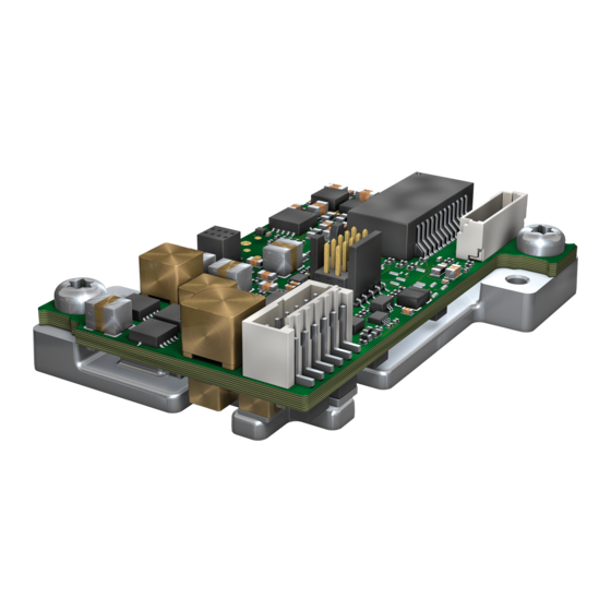
- Page 1 ETAS FETK-S1.1 Emulator Probe for Infineon AURIX MCU Family User Guide...
-
Page 2: Fetk-S1.1
Copyright The data in this document may not be altered or amended without special notification from ETAS GmbH. ETAS GmbH undertakes no further obligation in relation to this document. The software described in it can only be used if the customer is in possession of a general license agreement or single license. -
Page 3: Table Of Contents
Timer Triggering ..............23 ETAS FETK-S1.1 | User Guide... - Page 4 Mounting the FETK-S1.1 into the ECU Housing ........
- Page 5 ETAM2 Adapter ..............57 ETAS FETK-S1.1 | User Guide...
- Page 6 Index ................68 ETAS FETK-S1.1 | User Guide...
-
Page 7: Safety Information
Program codes or program control sequences that are created or changed via ETAS products, as well as all types of data obtained through the use of ETAS prod- ucts, must be checked for their reliability and suitability prior to use or distribution. -
Page 8: Intended Use
Shut down a damaged product immediately. The product cannot be repaired. Dispose of the product properly. Do not open or alter the product. Only ETAS may make changes to the product. -
Page 9: Safety Information
If the firmware update is not completed successfully, try it again. If a new firmware update is not possible and the product is not functional, send the product to ETAS. 1.3.3 Electrical Connection... -
Page 10: Connection To The Power Supply
2. Remove all cables from the product. 1.3.4 Cables and Accessories Cables - Only use ETAS cables, cables recommended by ETAS or other cables certi- fied for the application. - Route the cables such that they are protected against abrasion, damage, deformation and kinking. -
Page 11: Transport
11 | Safety Information Accessories Use ETAS accessories, accessories recommended by ETAS or other accessories certified for the application. For detailed information about accessories, see “Cables and Accessories” on page 47. 1.3.5 Transport - Only transport and store the product in ESD packaging. -
Page 12: Taking The Product Back And Recycling
1.6.1 CE Declaration of Conformity (European Union) With the CE mark attached to the product or its packaging, ETAS confirms that the product corresponds to the applicable product-specific European Directives. The CE Declaration of Conformity for the product is available upon request. -
Page 13: People's Republic Of China
13 | Safety Information ETAS confirms that the product corresponds to this directive which is applicable in the European Union. 1.7.2 People’s Republic of China ETAS confirms that the product meets the product-specific applicable guidelines of the China RoHS (Management Methods for Controlling Pollution. Caused by Electronic Information Products Regulation) applicable in China with the China RoHS marking affixed to the product or its packaging. -
Page 14: Introduction
SBRAM sense Pinless triggering Timer triggering To access the ECU the FETK-S1.1 has to be connected via ETAS ES89x ECU and Bus Interface Modules. The system can be used for high-speed Measurement, Calibration and ECU flash programming. Support of Rapid Prototyping applications e.g. functional prototyp- ing - bypass depends on the functionality of the connected modules. -
Page 15: Features
• Pull CalWakeUp until Startup Handshake: duration of the Wake up mech- anism is configurable 2.2.4 ECU Flash Programming via FETK - Using microcontroller debug interface, ECU software support not neces- sary - Braindead flashing under ProF control ETAS FETK-S1.1 | User Guide... -
Page 16: Further Characteristics
FETK or ECU is not necessary - Mounting possibilities inside or on top of ECU - Temperature range suitable for automotive application For more technical data on the FETK-S1.1 consult the chapter “Technical Data” on page 36. ETAS FETK-S1.1 | User Guide... -
Page 17: Hardware Description
Using an additional measurement data mem- ory area, the ECU microcontroller can provide data to the calibration and develop- ment system by buffering the data (DISTAB17) and triggering the FETK-S1.1 to read the data via DAP. -
Page 18: Ecu Interface
Ethernet interface (ETAS module or PC) ECU Interface The FETK-S1.1 is connected via connectors CON1 and CON2 to the ECU with two adapter cables (refer to Fig. 3-2 on page 19). The pin definition depends on the application and the microcontroller type. In general the ECU interface consists of... -
Page 19: Fetk Ethernet Interface
The FETK Ethernet interface utilizes a proprietary Ethernet protocol and is com- patible only with the Gigabit Ethernet interfaces of the ES89x ECU Interface Module. CON3 Fig. 3-4 Location of the FETK Ethernet Interface Connector (CON3) ETAS FETK-S1.1 | User Guide... -
Page 20: Dap Interface
The input voltage may vary (see chapter 7.5 on page 39). In case of higher input voltages to the FETK, additional voltage protection is required. The FETK-S1.1 will also accept voltage dips down to 3 V (for additional details of low voltage operation, see ISO standard 16750). -
Page 21: Ecu Voltage Supervisor
FETK pin VDDSBRAM. Data Emulation and Data Measurement The FETK-S1.1 is a serial FETK using DAP as the primary microcontroller interface. Typical of all serial ETKs, XETKs and FETKs, the RAM used for data emulation and data measurement is not accessible by the FETK until the microcontroller is pow- ered up and the startup handshake is performed. -
Page 22: Trace Based Measurement
The FETK-S1.1 can access both the Reference Page and the Working Page, regard- less of which is active from the microcontroller’s point of view. Another important restriction is that no access to the memory is possible, while the ECU is not running. -
Page 23: Pinless Triggering
3.11.1 Trace Triggering The FETK-S1.1 provides support for up to 255 trace triggers. The trace triggers are defined within a section of RAM covered by a trace window. Both the trace window and trace triggers are defined in the FETK-S1.1 configuration and/or A2L file. A write... -
Page 24: Reset
- the write must be 32 bit width (the upper 24 bits must be ‘0’) - the value 0x0 is not a valid trigger number NOTE It is not possible to use the FETK-S1.1 configured with trace triggers and a debug- ger with program / data trace simultaneously. 3.12 Reset The requirement for the FETK-S1.1 reset mechanism is to ensure that power-up... -
Page 25: Installation
This chapter contains information about the following topics: • Mounting the FETK-S1.1 into the ECU Housing ......25 •... -
Page 26: Fig. 4-1 Fetk-S1.1 Threads And Heat Spreader
NOTE Use the Fig. 7-7 on page 45 as a drilling template to prepare the ECU hous- ing with machined holes aligning with FETK-S1.1 hole pattern. Preparing the FETK-S1.1 2. Apply a thin layer of heat conductive paste to the bottom side of the FETK- S1.1 heat spreader. - Page 27 27 | Installation 1. Align the threaded drill holes of the FETK-S1.1 to the openings in the ECU housing. 2. Insert the screws into the holes in the ECU housing. 3. Screw the screws into the FETK-S1.1. NOTE Screw the two parts together without getting them off-thread.
-
Page 28: Connection To The Ecu
28 | Installation Connection to the ECU For connecting the FETK-S1.1 to the ECU two FETK adapter cables are recom- mended: - at CON1 adapter cable ETAM8A or ETAM8B (see chapter 3.12 on page 24 and chapter 8.9 on page 55) -
Page 29: Wiring
Gigabit Ethernet interfaces of the ES89x ECU Interface Module. 4.3.2 Power Supply The FETK-S1.1 needs a permanent power supply. DANGER Undefined vehicle behavior due to an ECU reset If the external power supply to the ETK is interrupted (e.g. cut, disconnected, etc.), this may lead to the ECU being reset. -
Page 30: Permanent Power Supply Inside Ecu Available
ECU G N D FETK EC U V eh icle C o n n e cto r Battery EC U Fig. 4-6 FETK-S1.1 Power Supply wiring with CBAM300.3 Cable Cable Gland Serial ETK Interface Connector Cable CBAM320.1 Cable CBAM320.1 E.g. Cable CBE260 Vehicle... -
Page 31: Permanent Power Supply Inside Ecu Not Available
Power Supply Connector Wiring ECU GND FETK Vehicle Connector Battery Fig. 4-8 FETK-S1.1 Power Supply wiring with CBAM350.1 Cable Permanent Power Supply inside ECU not available Cable Gland Serial FETK Interface Connector Cable CBAM305.1 Cable CBE260 Cable CBAM305.1 Cable K70... -
Page 32: Fig. 4-10 Isolated Power Supply Inside Ecu
32 | Installation Isolated Power Supply inside ECU The FETK-S1.1 does not require a galvanically isolated power supply. For special applications ETAS can offer a isolated power supply unit. Power Supply Connector Isolated Power Supply Permanent Supply Input Cable ETAM2 Cable ETAM 2 4,8 V«... -
Page 33: Etk / Xetk / Fetk Configuration
ETK / XETK / FETK is checked for the appropriate configuration. If necessary, the ETK / XETK / FETK will be configured appropriately to the corre- sponding project. ETAS FETK-S1.1 | User Guide... -
Page 34: Configuration Parameter
The XCT help window opens. 3. Choose Reference to User Interface > (X)ETK Hardware Configuration Parameters. 4. Choose the topic FETK-S1.1. The topic FETK-S1.1 contains information about the FETK-S1.1 hardware configuration parameters and their possible values. ETAS FETK-S1.1 | User Guide... -
Page 35: Troubleshooting
ECU and ETK can be established. Workaround: Trigger an ECU reset by application tool. NOTE The FETK-S1.1 requires a permanent power supply. It is typically powered directly from the car battery. Refer to chapter “Power Supply” on page 29. ETAS FETK-S1.1 | User Guide... -
Page 36: Technical Data
• Mechanical Dimensions ..........45 System Requirements 7.1.1 ETAS Compatible Hardware ETAS Hardware: ES89x ECU Interface Modules 7.1.2 PC with one Ethernet Interface A PC with one open Ethernet interface (1 Gbit/s) with RJ45 connection is required to connect the ES89x module. -
Page 37: Software Support
37 | Technical Data 7.1.3 Software Support You need the following software versions to support the FETK-S1.1. Operating the FETK-S1.1 with older software versions is not possible. FETK-S1.1A Microcontroller INCA ETK Tools ASCET- INTECRIO TC26x-ED V11.8.0 V7.2.8 V4.1.9 V6.4.3 V4.6.2 TC26x-PD V11.8.0 V7.2.8... -
Page 38: Data Emulation And Measurement Memory
7.2.1 Data Emulation Memory and Microcontroller Support The FETK-S1.1 uses a portion of or up to the entire size of the ED RAM, to emulate data in internal flash. The following table lists the supported microcontrollers, the size of the ED RAM, and states if the ED RAM is capable of being powered using a standby supply. -
Page 39: Environmental Conditions
2 A 58V DC, e.g. Littelfuse 0997002.WXN The FETK-S1.1 implements reverse voltage protection in the same range and may be used only with central load dump protection. 24 V vehicles require U disturbing pulse reduction to 12 V vehicle system. -
Page 40: Microcontroller Interface
NOTE DAP timing parameters in this chapter refer to the DAP interface (CON1) of the FETK-S1.1. The DAP wiring to the ECU (ETAM8) must be taken account addition- ally. All timings are measured at a reference level of 1.5 V. Output signals are mea- sured with 20 pF to ground and 50 ... -
Page 41: 2-Pin Dap Mode
50 MHz DAP Clock Frequency (ETK --> Target) DAP1/DAP2 Set-Up Time ETK --> Target) DAP1/DAP2 Hold Time (ETK --> Target) DAP1/DAP2 Clock-to- Undetermined, ETK automati- Out Time (Target --> cally determines optimum ETK) sampling point ETAS FETK-S1.1 | User Guide... -
Page 42: Electrical Characteristics
Electrical Characteristics 7.9.1 ECU Interface Connector Signal Pin Type V (max) (min) (max) (min) (max) Leakage current Additional (max) [V] (min / max) load by ETK [A] (typ) [pF] DAP0 +745 / +475 DAP1 +5000 / +3340 DAP2 +5000 / +3340 Reserved +20 / -20 /TRST... -
Page 43: Pin Assignment
Pin Assignment NOTE The tables describe the pin assignment at the ETK side. CON2 CON3 CON1 Fig. 7-3 Location of the FETK-S1.1 Interfaces 7.10.1 ECU Interface Connector CON1 (JTAG Mode) CON1 Fig. 7-4 ECU Inteface Connector CON1 Signal Direction Comment... -
Page 44: Power Supply Connector Con2
Input Vehicle battery Ubatt1 Input Vehicle battery NOTE VDDSTBY may not be used as power supply of the microcontroller core. VDDSTBY is permanently available and must be used as power supply of the ED-RAM, only. ETAS FETK-S1.1 | User Guide... -
Page 45: Fetk Ethernet Interface Connector Con3
Length 46.00 1.811 Width 37.00 1.4567 Height 13.10 0.5157 : CBAM300/ CBAM305/ CBAM340 mounted at CON3 7.11.1 Top View Fig. 7-7 FETK-S1.1 Dimensions - Top View Item Dimension Tolerance Dimension Tolerance [Millimeters] [Inches] [Inches] [Millimeters] 41.50 +/- 0.20 1.634 +/- 0.008 35.90... -
Page 46: Side View
1.220 +/- 0.004 28.00 +/- 0.20 1.102 +/- 0.008 3.00 +/- 0.20 0.118 +/- 0.008 7.11.2 Side View Fig. 7-8 FETK-S1.1 Dimensions - Side View Item Dimension Tolerance Dimension Tolerance [Millimeters] [Inches] [Inches] [Millimeters] 4.20 +/- 0.10 0.165 +/- 0.004 1.60... -
Page 47: Cables And Accessories
See chapter 4.2 on page 28 for details on wiring the ECU interface adapt- ers. NOTE We recommend to use ETAS cables or any other cables certified by the standards for the application. Adhere to the maximum permissible cable lengths! NOTE Application-specific cables are available from ETAS. -
Page 48: Cbam300 Cable
Shield ECU housing 8.3.3 Temperature Range Condition Temperature Operating temperature -40 °C to +125 °C 8.3.4 Tightness Condition IP Code PG9 screwing IP67 8.3.5 Ordering Product Length Order Number CBAM300.3-0m6 0.6 m F 00K 112 469 ETAS FETK-S1.1 | User Guide... -
Page 49: Cbam320 Cable
8.4.3 Temperature Range Condition Temperature Operating temperature -40 °C to +125 °C 8.4.4 Tightness Condition IP Code M9 x 0.6 screwing IP67 8.4.5 Ordering Product Length Order Number CBAM320.1-0m6 0.6 m F 00K 109 299 ETAS FETK-S1.1 | User Guide... -
Page 50: Cbam340 Cable
Gbit Ethernet cable, e.g. CBE260 CON2 White FETK CON3 Shield to ECU housing 8.5.3 Temperature Range Condition Temperature Operating temperature -40 °C to +125 °C 8.5.4 Ordering Product Length Order Number CBAM340.1-0m6 0.6 m F 00K 109 302 ETAS FETK-S1.1 | User Guide... -
Page 51: Cbam350 Cable
(not included in the delivery). NOTE The Lemo Spanner DCH.91.161.PA is not included in the cable delivery, It need to be ordered separately. For detailed information on mounting accessories con- tact ETAS technical support. ETAS FETK-S1.1 | User Guide... -
Page 52: Temperature Range
For mounting the cable, cut a PG9 thread into the ECU housing. For thin-walled housings use a nut SM-PE 9. It is available from Lapp (order number: 52103210). 8.7.2 Dimensions Fig. 8-9 CBAM305.1-0m6 Cable - Dimensions ETAS FETK-S1.1 | User Guide... -
Page 53: Connectors
FETK UBATT Connector Color Target CON1 Blue lila Gbit Ethernet cable, e.g. CBE260 CON2 White FETK CON3 Black Permanent power supply, K70.1 cable CON4 2 pin ERNI power ECU connector Fig. 8-12 CBAM305.1-2m2 - Connectors ETAS FETK-S1.1 | User Guide... -
Page 54: Temperature Range
Gigabit Ethernet and Power Connection cable for FETK. Lemo connectors on both sides compliant to IP65. 3 m length. The CBE260 cable is a Gigabit Ethernet cable to connect an ETAS ES device with an FETK or another ES device. The cable supports power propagation. -
Page 55: Temperature Range
There are two variants for the ETAM8 adapter available: - ETAM8A hold the ECU in Reset, while the ETK is booting. - ETAM8B do not pull the Reset low while booting. With a ETAM8B adapter the FETK-S1.1 has the same reset behavior like FETK- T1.0. NOTE See chapter "Installation"... -
Page 56: Ecu Connector: Signal Modes
Power Supply Cable ETV5 8.10.1 Usage The ETV5 cable is an open wire power supply cable with one battery and GND con- nection. NOTE For better power integrity cut the cable to the shortest possible length. ETAS FETK-S1.1 | User Guide... -
Page 57: Pin Assignment
0.25 m F 00K 111 701 8.11 ETAM2 Adapter Fig. 8-19 FETK - ECU Adapter ETAM2 NOTE See chapter "Installation" for details on mating connector to the ETAM2. 8.11.1 Pin Assignment Fig. 8-20 ETAM2 Connector ETAS FETK-S1.1 | User Guide... -
Page 58: Ecu Signals
5 mm stripped and Molex tinned Side A Medi cable Side C Side B Position Color Position Position Blue Yellow Brown Green 8.12.2 Ordering Product Length Order Number ETAM5 0.136 m F 00K 110 101 ETAS FETK-S1.1 | User Guide... -
Page 59: Etam9 Adapter
8.13.3 Temperature Range Condition Temperature Range Operating temperature -40 °C to +110 °C 8.13.4 Order Information Product Length Order Number ETAM9 F/XETK-S ECU Adapter, MOLEX - MOLEX (6fc 0.136 m F 00K-111-043 - 5fc), 0m136 ETAS FETK-S1.1 | User Guide... -
Page 60: Etam10 Adapter
ETAM10 adapts the ETK power signals (Molex 6 pin connector) to an ECU with a 6 pin Molex PicoSpox connector. The ECU connector is available as Vertical SMT Header [87437-0643] or Right Angle SMT Header [87438-0643]. 8.14.2 Dimensions Fig. 8-24 ETAM10 Adapter Dimensions ETAS FETK-S1.1 | User Guide... -
Page 61: Ecu Signals
8.14.4 Temperature Range Condition Temperature Range Operating temperature -40 °C to +110 °C 8.14.5 Order Information Product Length Order Number ETAM10 F/XETK-S ECU Adapter, MOLEX - MOLEX 0.07 m F 00K-111-814 (6fc - 6fc), 0m07 ETAS FETK-S1.1 | User Guide... -
Page 62: Ordering Information
- China-RoHS-leaflet_Compact_cn Cable NOTE We recommend to use ETAS cables or any other cables certified by the stan- dards for the application. Adhere to the maximum permissible cable lengths! Please contact your local ETAS representative for further cable information. NOTE The cables shown in chapter “Cables and Accessories”... -
Page 63: Ecu Adapter Cable
ETAM8A BR_XETK-S3 ECU Adapter, FCI - SAM- ETAM8A F 00K 110 754 TEC SFM (20c - 10fc), 0m11 ETAM8B BR_XETK-S3 ECU Adapter, FCI - SAM- ETAM8B F 00K 110 881 TEC SFM (20c - 10fc), 0m11 ETAS FETK-S1.1 | User Guide... -
Page 64: Power Supply Cable
ETAM10 F/XETK-S ECU Adapter, MOLEX - ETAM10 F 00K 111 814 MOLEX (6fc - 6fc), 0m07 Power Supply For special applications ETAS can offer a isolated power supply unit. For detailed information contact ETAS technical support. ETAS FETK-S1.1 | User Guide... -
Page 65: Contact Information
65 | Contact Information Contact Information Technical Support For details of your local sales office as well as your local technical support team and product hotlines, take a look at the ETAS website: www.etas.com/en/hotlines.php ETAS Headquarters ETAS GmbH Borsigstraße 24... -
Page 66: Figures
Fig. 4-7 FETK-S1.1 Power Supply wiring with CBAM320.1 Cable ......30 Fig. 4-8 FETK-S1.1 Power Supply wiring with CBAM350.1 Cable . - Page 67 ETAM10 Adapter Dimensions ........... . 60 ETAS FETK-S1.1 | User Guide...
-
Page 68: Index
PC network adapter ....36 Pin Assignment ..... . 43 ETAS FETK-S1.1 | User Guide...
Need help?
Do you have a question about the FETK-S1.1 and is the answer not in the manual?
Questions and answers