
Subscribe to Our Youtube Channel
Related Manuals for ETAS XETK-S23.0


Summary of Contents for ETAS XETK-S23.0
- Page 1 ETAS XETK-S23.0 - User Guide JTAG Emulator Probe for TI C2000 Microcontrollers User Guide...
- Page 2 The data in this document may not be altered or amended without special noti- fication from ETAS GmbH. ETAS GmbH undertakes no further obligation in relation to this document. The software described in it can only be used if the customer is in possession of a general license agreement or single license.
-
Page 3: Table Of Contents
XETK-S23.0 JTAG Interface........ - Page 4 7.1.3 XETK-S23.0 Software Support........33 Data Emulation and Measurement Memory.
- Page 5 XETK-S23.0 ........
-
Page 6: About This Document
The target to be achieved is defined in the heading. The necessary steps for this are in a step-by-step guide: Target definition 1. Step 1 2. Step 2 3. Step 3 > Result Presentation of Supporting Information NOTE Contains additional supporting information. XETK-S23.0 - User Guide... -
Page 7: Basic Safety Notices
Use of Open Source Software........12 General Safety Information Please observe the Product Safety Notices ("ETAS Safety Notice") and the fol- lowing safety notices to avoid health issues or damage to the device. - Page 8 Do not use the product in a wet or damp environment. Do not use the product in potentially explosive atmospheres. Keep the surfaces of the product clean and dry. XETK-S23.0 - User Guide...
- Page 9 CAUTION Risk of short circuiting the internal signals of the ETK! When you mount the ETK to the ECU, you must ensure that the screws and washers used will not penetrate the ETK printed circuit board. XETK-S23.0 - User Guide...
-
Page 10: Identifications On The Product
Cabling Use exclusively ETAS cables at the connections of the product! Adhere to the maximum permissible cable lengths! Observe the assignment of the cables to the connectors! Detailed information about cabling is located in the ETK User Guides. -
Page 11: Taking The Product Back And Recycling
For more information on the ETAS GmbH Recycling software, contact the ETAS sales and service locations. CE Conformity With the CE mark attached to the product or its packaging, ETAS confirms that the product corresponds to the product-specific, applicable directives of the European Union. -
Page 12: Rohs Conformity
For individual electronic components used in our products, there are currently no equivalent alternative substances, which is why we make use of the exception 7C-I in Annex III of this Directive. ETAS confirms that the product corresponds to this directive which is applica- ble in the European Union. China... -
Page 13: Introduction
The XETK-S23.0 supports the standard full duplex 100Base-T Ethernet inter- face and can be connected directly or via ES59x/ES600/ES89x/ES910 modules to the PC. No additional ETAS modules are required for the access to the ECU. The XETK-S23.0 can be used for rapid prototyping applications (bypass) as well as for measurement and calibration applications. -
Page 14: Features
µs – Measurement raster down to 100 • “ETK Drivers and Tools” update to support ETAS software tools (INCA, XCT) • Firmware update (programming of the logic device) through HSP soft- ware service packs; removal of XETK or ECU is not necessary •... -
Page 15: Hardware Description
XETK-S23.0 JTAG Interface ........21... -
Page 16: Ecu Interface
PC. The 100 Mbit/s XETK Ethernet interface provides communication with the PC. The power supply for the XETK-S23.0 is provided by a switch mode power sup- ply, to minimize power dissipation. -
Page 17: Xetk Ethernet Interface
XETK Ethernet Interface The XETK Ethernet interface can be directly connected to the PC via CON2 (refer to Fig. 4-3). No additional ETAS module is required for the access to the ECU. The interface is a standard full duplex 100Base-TX Ethernet interface using the XCP protocol. -
Page 18: Ecu Voltage Supervisor
From the input battery voltage, the XETK-S23.0 creates all necessary voltages through switching power supplies on the XETK-S23.0. The power supply of the ECU is not affected by the XETK-S23.0. An automatic switch ensures that the power supply of the XETK-S23.0 is automatically switched on and off when the XETK enters and leaves its standby (sleep) mode. -
Page 19: Status Leds
- data retention of the calibration data manager in the ECU is no longer ensured - as soon as the XETK-S23.0 switches on again, the ECU switches to the Reference Page. Green LED stays on until the calibration and development system downloads data into the calibration data memory. -
Page 20: Data Emulation And Data Measurement
Hardware Description Data Emulation and Data Measurement The XETK-S23.0 is a serial XETK using JTAG as the primary microcontroller interface. Typical for all serial (X)ETKs, the RAM used for data emulation and data measurement is not accessible by the XETK until the microcontroller is powered up and the startup handshake is performed. -
Page 21: Xetk-S23.0 Jtag Interface
Equivalent Circuitry of the ECU JTAG Interface (ECU) The ECU part of the JTAG XETK interface is depicted in Fig. 4-6. The XETK-S23.0 incorporates 22 Ohm series resistors for the TMS, TCK, TDI and /TRST lines on the ECU interface. Hence, no additional termination resis- tors are required on the ECU for these signals. -
Page 22: Trigger Modes: Overview
ETAS Hardware Description Trigger Modes: Overview The XETK-S23.0 supports the following trigger modes: • Pinless triggering • Timer triggering The trigger mode "Pinless Triggering" uses the microcontroller’s RAM addresses for triggering. See chapter “Pinless Triggering” on page 22 for fur- ther details. -
Page 23: Reset
ECU is clean and smooth. The XETK-S23.0 drives / PORESET low during XETK power up or upon INCA request. The XETK-S23.0 senses the status of the /PORESET line to detect when the ECU is in reset. If configured, and the microcontroller has /RESETOUT, the XETK-S23.0 can also be used to sense the status for the ECU reset. -
Page 24: Installation
This chapter contains information about the following topics: • Mounting the XETK-S23.0 to the ECU ......24 •... -
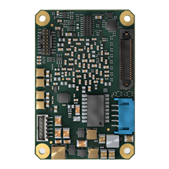
Page 25: Fig. 5-1 Xetk-S23.0 Bottom Side View
ETAS Installation 5.1.1.1 Mounting Materials For mounting the XETK-S23.0 to the ECU housing, the following parts are sug- gested: • 4x screws M2.5 • XETK-S23.0 • Gap Pad, as supplied with the XETK-S23.0 or available as a spare part. •... -
Page 26: Mounting The Xetk-S23.0 To The Ecu Metal Housing
Thermal transfer from the XETK to the ECU housing! When you mount the XETK to the ECU, you must ensure that a constant gap of 3 mm is maintained between the XETK-S23.0 PCB and the flat surface of the ECU housing. -
Page 27: Electrical Connection To The Ecu
When you mount the XETK to the ECU, you must ensure that the screws and washers used will not penetrate the XETK printed circuit board. For connecting the XETK-S23.0 to the ECU, two XETK adapter cables are rec- ommended: •... -
Page 28: Wiring
E S 5 9x E S 8 9 x Fig. 5-7 Wiring - XETK Ethernet Interface The XETK Ethernet interface can be directly connected to the PC. No additional ETAS module is required for the access to the ECU. XETK-S23.0 - User Guide... -
Page 29: Power Supply
Fig. 5-9 Permanent Power Supply inside ECU not available Isolated Power Supply inside ECU The XETK-S23.0 does not require a galvanically isolated power supply. For spe- cial applications ETAS offers the isolated power supply ETP2. Power Supply Connector Permanent Supply... -
Page 30: Xetk Configuration
If these parameters are entered correctly in the corresponding ECU description file, it guarantees that every time the calibration system is started, the XETK is checked for the appropriate configuration. If necessary, the XETK will be con- figured appropriately to the corresponding project. XETK-S23.0 - User Guide... -
Page 31: Configuration Parameter
The XCT Tool help window opens. 3. Choose Reference to User Interface (X)ETK Hardware Configuration Parameters. 4. Choose the topic XETK-S23.0. The topic XETK-S23.0 contains information about the XETK- S23.0 hardware configuration parameters and their possible values. XETK-S23.0 - User Guide... -
Page 32: Technical Data
Adapter the used network adapter by double-click. Deactivate the "Allow the computer to turn off this device to save power" option in the "Power Manage- ment" register. Confirm your configuration. The manufacturers of network adapter have different names for this function. XETK-S23.0 - User Guide... -
Page 33: Xetk-S23.0 Software Support
7.2.1 Data Emulation Memory and Microcontroller Support The XETK-S23.0 can use any available RAM to emulate data in internal flash. The following table lists the supported microcontrollers, and the available emu- lation RAM, and states if the EMU RAM is capable of being powered using a standby supply. -
Page 34: Measurement Data Memory
- 40 °C to +110 °C/ - 40 °F to +230 °F Temperature range (storage) 0 °C to +50 °C/ - 18 °F to +122 °F Relative humidity (non-condensing) 0 to 95% Operating altitude max. 5000 m/ 16400 ft XETK-S23.0 - User Guide... - Page 35 ETAS Technical Data Item Characteristics Contamination level Degree of protection Determined by installation in ECU Overvoltage category (AC mains supply) XETK-S23.0 - User Guide...
-
Page 36: Power Supply
12 V vehicle system. Batt 12 V vehicles don’t require special disturbing pulse reductions. NOTE The XETK-S23.0 will accept permanent power supply voltage dips (for addi- tional details of 3 V low voltage operation, see ISO standard 16750). XETK-S23.0 - User Guide... -
Page 37: Test Characteristics
NOTE JTAG timing parameters in this chapter refer to the JTAG interface (CON1) of the XETK-S23.0. The JTAG wiring to the ECU (ETAN1) must be taken into account additionally. All timings are measured at a reference level of 1.5 V. Output signals are mea- sured with 20 pF to ground and 50 ... -
Page 38: Jtag Timing Parameters
Minimum 12 ns required hold (ETK --> Target) for microcontroller TDO clock-to-out time 3.5 (min.) Minimum 2.25 ns do_min (Target --> ETK) required by microcontrol- ler specification 30 (max) Maximum 30 ns by do_max microcontroller specifica- tion XETK-S23.0 - User Guide... -
Page 39: Electrical Characteristics
Electrical Characteristics 7.9.1 ECU Interface Characteristics Parameter Symbol Condition Unit CalWakeUp Output Voltage CALWAKEUP = 6.6 - 32 V; - 1 V Batt Batt Batt load 0 - 50 mA ECU Power Supply Supervision VDD 2.55 2.58 2.60 Voltage (3.3 V selected) VDD ... -
Page 40: Ecu Interface Connector Con1 (5.0 V Interface Selected)
7.9.2 ECU Interface Connector CON1 (5.0 V Interface selected) Signal Pin Type (max) (min) (max) (max) (min) (max) Leakage current Add. Load [A] by XETK (typ) [pF] +/-10 /TRST +/-10 +5200/+3830 +1135/+840 +/-30 /PORST XIOD +25/-20 RSVD3 +25/-20 RSVD2 +/-13 RSVD1 +/-10 Pin Type: I: Input, X: Tristate, O: Output, OD: Open Drain... -
Page 41: Ecu Interface Connector Con1 (3.3 V Interface Selected)
7.9.3 ECU Interface Connector CON1 (3.3 V Interface selected) Signal Pin Type (max) (min) (max) (max) (min) (max) [V] Leakage current Add. Load [A] by XETK (typ) [pF] 0.55 3.45 +/-10 /TRST 0.55 3.45 +/-10 0.55 3.45 +3460/+2010 0.55 3.45 +704/+411 +/-30 /PORST... -
Page 42: Pin Assignment
ETAS Technical Data 7.10 Pin Assignment 7.10.1 ECU Interface Connector CON1 (XETK-S23.0 Side) Pin Signal Direction Comment TX0_P Not used on XETK-S23.0 VDD (Sense) Sense for Switched power supply of ECU (ignition) TX0_N Not used on XETK-S23.0 JTAG Clock signal... -
Page 43: Interface And Power Supply Connector Con4
ETAS Technical Data Pin Signal Direction Comment AUDDATA1 Not used on XETK-S23.0 FLMD0 Flash Mode 0 AUDDATA2 Not used on XETK-S23.0 AUDSYNC Not used on XETK-S23.0 AUDDATA3 Not used on XETK-S23.0 7.10.2 Interface and Power Supply Connector CON4 Signal Direction Comment... -
Page 44: Mechanical Dimensions
ETAS Technical Data 7.11 Mechanical Dimensions The reference measure for all drawings is millimeters ØH Fig. 7-1 XETK-S23.0 Dimensions - Top View Item Dimension Tolerance Dimension Tolerance [mm] [mm] [in] [in] 60.00 +/- 0.20 2.362 +/- 0.008 56.50 +/- 0.20 2.224... -
Page 45: Cables And Accessories
PC Interface Cable ..........48 • ETAS Module Interface Adapter Cable ......49 •... -
Page 46: Cbam271 Adapter Cable
ECU- housing, Lemo 1B PHE - JST PHR (10fc-5fc), 0.5 m length. Fits for ETKS_C3 case. NOTE For mounting the cable, cut a PG9 thread into the ECU housing. For thin- walled housings use a nut SM-PE 9. Available from Lapp, Order number: 52103210. Product Length CBAM271.1-0m5 0.5 m XETK-S23.0 - User Guide... -
Page 47: Combined Interface And Power Supply Cable
ECU! NOTE For mounting the cable, cut a PG9 thread into the ECU housing. For thin- walled housings use a nut SM-PE 9. Available from Lapp, Order number: 52103210. XETK-S23.0 - User Guide... -
Page 48: Pc Interface Cable
CBE200-3 Cable Product Length CBE200-3 8.3.2 CBAE200 Adapter Cable Fig. 8-7 CBAE200 Adapter Cable Cable adapter to connect CBE230 cable to the PC over an RJ45 connector. The CBAE200.2-1m20 supports Gigabit Ethernet. Product Length CBAE200.2-1m20 1.20 m XETK-S23.0 - User Guide... -
Page 49: Etas Module Interface Adapter Cable
Cables and Accessories ETAS Module Interface Adapter Cable 8.4.1 CBE230 Cable Fig. 8-8 CBE230 Cable Gigabit Ethernet connection cable for ETAS devices. IP67 rated Lemo connec- tors on both sides. Gigabit Ethernet cable with power supply. Product Length CBE230.1-3 CBE230.1-8 8.4.2... -
Page 50: Power Supply Cables
ETAS Cables and Accessories Power Supply Cables 8.5.1 Cable K70.1 Fig. 8-10 Power Supply Cable K70.1 Millimeters Inches 2000 78.74 8.5.2 Power Supply Cable KA50 Fig. 8-11 Power Supply Cable KA50 Millimeters Inches 7.87 1.97 XETK-S23.0 - User Guide... -
Page 51: Ecu Interface Adapters
Inches 250.00 9.84 8.6.2 XETK - ECU Adapter ETAM5 A Fig. 8-13 XETK - ECU Adapter ETAM5 Millimeters Inches 136.0 5.35 NOTE See Fig. 5-6 on page 27 for details on mating connector to the ETAM5. XETK-S23.0 - User Guide... -
Page 52: Xetk - Ecu Adapter Etam9
NOTE See Fig. 5-6 on page 27 for details on mating connector to the ETAN4. ETAN4 Pin Assignment Pin Signal Description Signal Ground JTAG TCK signal /TRST JTAG /TRST signal JTAG TDO signal JTAG TMS signal XETK-S23.0 - User Guide... - Page 53 ECU reset signal (open drain) for reset assertion and supervision 11 VSTBY (Sense) Sense the supply of the standby (WP) RAM 12 /RESETOUT ECU Internal Reset Status (sense) NOTE For additional details on the ETAN4 cable, please request the ETAN4 User Guide. XETK-S23.0 - User Guide...
-
Page 54: Waterproof Case Etks_C3
ETAS Cables and Accessories Waterproof Case ETKS_C3 For mounting the XETK-S23.0 on top of ECUs, an external case is available. It is small, robust and waterproof (IP65). Fig. 8-16 ETKS_C3 Top View Fig. 8-17 ETKS_C3 Bottom View Fig. 8-18 ETKS_C3 Side View... -
Page 55: Ordering Information
Order Name Short Name Order Number Isolated Power Supply Interface for XETK ETP2 F 00K 104 010 Mounting Material Order Name Short Name Order Number Gap Pad as spare part for XETK-S23.0 XETK-S22_GP F 00K 111 041 XETK-S23.0 - User Guide... -
Page 56: Cables
ETAS Ordering Information Cables Please contact your local ETAS representative for further cable information. NOTE The cables showed in chapter “Cables and Accessories” on page 45 are not included in the XETK-S23.0 delivery. 9.5.1 ECU Adapter Cables NOTE The hardware for mounting ECU adapter cable CBAM240.1 is not included in the cable delivery;... -
Page 57: Ethernet Cables
F 00K 000 940 Supply, with Filter Coil, Lemo 0B EGG - open wire (2fc-1c), 0m2 Waterproof Case Order Name Short Name Order Number waterproof case, designed for XETK-S4.x, ETKS_C3 F 00K 107 683 ETK-S6.x and XETK-S2x XETK-S23.0 - User Guide... -
Page 58: Contact Information
Germany Internet: www.etas.com ETAS Subsidiaries and Technical Support For details of your local sales office as well as your local technical support team and product hotlines, take a look at the ETAS website: ETAS subsidiaries Internet: www.etas.com/en/contact.php ETAS technical support Internet: www.etas.com/en/hotlines.php... -
Page 59: Figures
XETK-S23.0 Dimensions - Side View ........44... - Page 60 ETKS_C3 Side View ...........54 XETK-S23.0 - User Guide...
-
Page 61: Index
Cables ......45 ECU ......16 XETK-S23.0 - User Guide...
Need help?
Do you have a question about the XETK-S23.0 and is the answer not in the manual?
Questions and answers