
Related Manuals for ETAS FETK-S2.1


Summary of Contents for ETAS FETK-S2.1
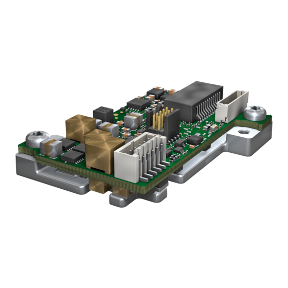
- Page 1 FETK-S2.1 Emulator Probe for MPC57xx and EMU57xx MCU Family User’s Guide www.etas.com...
-
Page 2: Fetk-S2.1
The data in this document may not be altered or amended without special noti- fication from ETAS GmbH. ETAS GmbH undertakes no further obligation in relation to this document. The software described in it can only be used if the customer is in possession of a general license agreement or single license. -
Page 3: Table Of Contents
Pull CalWakeUp until Startup Handshake ........26 FETK-S2.1 - User’s Guide... - Page 4 ETAS Compatible Hardware ........
- Page 5 ECU Signals ........... . 62 FETK-S2.1 - User’s Guide...
- Page 6 ETAS Contact Addresses ........
-
Page 7: About This Document
Presentation of Instructions The target to be achieved is defined in the heading. The necessary steps for this are in a step-by-step guide: Target definition 1. Step 1 2. Step 2 3. Step 3 > Result FETK-S2.1 - User’s Guide... -
Page 8: Typographical Conventions
General emphasis and new terms are set in dimensional table of sample italics. points. Hardware Bold Menu commands, buttons, labels of the product Italic Emphasis on content and newly introduced terms Presentation of Supporting Information NOTE Contains additional supporting information. FETK-S2.1 - User’s Guide... -
Page 9: Basic Safety Notices
• “Use of Open Source Software” on page 15 General Safety Information Please observe the Product Safety Notices ("ETAS Safety Notice") and the fol- lowing safety notices to avoid health issues or damage to the device. NOTE Carefully read the documentation (Product Safety Advice and this User's Guide) that belongs to the product prior to the startup. - Page 10 Application Area of the Product This product was developed and approved for automotive applications. For use in other application areas, please contact your ETAS contact partner. Requirements for Operation The following requirements are necessary for safe operation of the product: •...
- Page 11 CAUTION Risk of short circuiting the internal signals of the ETK! When you mount the ETK to the ECU, you must ensure that the screws and washers used will not penetrate the ETK printed circuit board. FETK-S2.1 - User’s Guide...
- Page 12 Cabling Use exclusively ETAS cables at the connections of the product! Adhere to the maximum permissible cable lengths! Observe the assignment of the cables to the connectors! Detailed information about cabling is located in the ETK User's Guides.
-
Page 13: Identifications On The Product
SN: yyxxxxx Serial number (7-digit) XXXX/YY Product version ZZZZ Year of manufacture ETAS GmbH, Manufacturer's address PO Box 300220, 70442 Stuttgart, Germany NOTE For symbols and product information one or several adhesive labels can be used. FETK-S2.1 - User’s Guide... -
Page 14: Taking The Product Back And Recycling
CE marking With the CE mark attached to the product or its packaging, ETAS confirms that the product corresponds to the applicable product-specific European Direc- tives. The CE Declaration of Conformity for the product is available upon request. -
Page 15: Declarable Substances
Some products from ETAS GmbH (e.g. modules, boards, cables) use compo- nents with substances that are subject to declaration in accordance with the REACH regulation (EU) no.1907/2006. Detailed information is located in the ETAS download center in the customer information "REACH Declaration" (www.etas.com/Reach). This information is continuously being updated. -
Page 16: Introduction
FETK-S2.1, and other details. Applications The FETK-S2.1 is an emulator probe for the NXP Freescale MPC57xx and for the STMicroelectronics EM57xx and EM58 microcontroller family. It is a serial FETK designed for use with the JTAG debug interface (IEEE/ISTO 5001). -
Page 17: Features
– Calibration Wake Up: Wake up mechanism to wake up the power sup- ply of the ECU via the Calibration Wake up pin – Pull CalWakeUp until Startup Handshake: duration of the Wake up mechanism is configurable FETK-S2.1 - User’s Guide... - Page 18 FETK or ECU is not necessary • Mounting possibilities inside or on top of ECU • Temperature range suitable for automotive application For more technical data on the FETK-S2.1 consult the chapter “Technical Data” on page 33. FETK-S2.1 - User’s Guide...
-
Page 19: Hardware Description
ETAS Hardware Description Hardware Description In this chapter, the function blocks of the FETK-S2.1 are explained in detail. Architecture Fig. 4-1 shows the block diagram of the FETK-S2.1. Tool Interface Configu‐ ration Flash Trigger Unit FETK Interface Wakeup Control Ethernet Unit Gbit/s Ethernet Traffic ... -
Page 20: Ecu Interface
Hardware Description ECU Interface The FETK-S2.1 is connected via connectors CON1 and CON2 to the ECU with two adapter cables (refer to Fig. 4-2 on page 20). The pin definition depends on the application and the microcontroller type. In general the ECU interface con- sists of •... -
Page 21: Fetk Ethernet Interface
The FETK Ethernet interface utilizes a proprietary Ethernet protocol and is compatible only with the Gigabit Ethernet interfaces of the ES89x ECU Inter- face Module. CON3 Fig. 4-4 Location of the FETK Ethernet Interface connector (CON3) FETK-S2.1 - User’s Guide... -
Page 22: Power Supply
ISO standard 16750). From the input battery voltage, switch-mode power supplies provide all neces- sary voltages on the FETK-S2.1. The power supply of the ECU is not affected by the FETK-S2.1. An automatic switch ensures that the power supply of the FETK-S2.1 is automatically switched on and off when the FETK enters and... -
Page 23: Data Emulation And Data Measurement
Hardware Description Data Emulation and Data Measurement The FETK-S2.1 is a serial FETK using JTAG as the primary microcontroller interface. The interface can switch to LFAST during handshake. Typical of all serial ETKs, XETKs and FETKs,the RAM used for data emulation and data mea- surement is not accessible by the FETK until the microcontroller is powered up and the startup handshake is performed. -
Page 24: Jtag And Lfast Interface
The FETK-S2.1 supports the JTAG mode for XCP debugger arbitration, test and calibration. Mode Debugger support MC support JTAG LFAST For LFAST mode the FETK-S2.1 starts at first in JTAG mode to switch into LFAST mode automatically. Trigger Modes: Overview The FETK-S2.1 supports the following trigger modes: • Pinless triggering •... -
Page 25: Pinless Triggering
50 µs default. The FETK then starts acquisition of appropriate measurement data based on which bits of the register are set. Active bits in "DTS_SEMAPHORE" are automatically cleared by the microcon- troller when the register is read by FETK. FETK-S2.1 - User’s Guide... -
Page 26: Timer Triggering
The signals /PORST and /RESETOUT of the microcontroller are used by the FETK-S2.1 to detect when the ECU is in reset. The FETK-S2.1 senses the switched ECU power supply. This allows it to detect when the ECU is off and forward this information to INCA. In addition, it allows the FETK to enter the power save mode with the calibration system unplugged. -
Page 27: Installation
When you mount the FETK to the ECU, you must ensure that the screws and washers used will not penetrate the FETK printed circuit board. For connecting the FETK-S2.1 to the ECU two FETK adapter cables are recom- mended: •... -
Page 28: Wiring
ETAS Installation Fig. 5-2 FETK-S2.1 Connection to the ECU Wiring 5.2.1 FETK Ethernet Interface Lemo Lemo Lemo 10 ( m) FETK 10 ( f) ES89x 10 ( m) CBE260.1‐3 CBAM300.1‐0m6 CBE260.1‐8 CBAM305.1‐0m6 CBAM340.1‐0m6 Fig. 5-3 Wiring - FETK Ethernet Interface The FETK Ethernet interface can be connected to the ES89x ECU and Interface Module. -
Page 29: Power Supply
ETAS Installation 5.2.2 Power Supply The FETK-S2.1 needs a permanent power supply. 5.2.2.1 Permanent Power Supply inside ECU available C able G land Se rial ETK Inte rface C onne ctor C able C B A M 300 .3 C a b le C B A M 300 .3 E.g. -
Page 30: Fig. 5-6 Fetk-S2.1 Power Supply Wiring With Cbam350.1 Cable
FETK-S2.1 Power Supply wiring with CBAM305.1 Cable 5.2.2.3 Isolated Power Supply inside ECU The FETK-S2.1 does not require a galvanically isolated power supply. For spe- cial applications ETAS can offer a isolated power supply unit. Power Supply Connector Isolated Power Supply... -
Page 31: Etk / Xetk / Fetk Configuration
ETAS ETK / XETK / FETK Configuration ETK / XETK / FETK Configuration The "ETK / XETK / FETK Configuration" chapter describes the FETK-S2.1 hard- ware configuration. Overview As already mentioned in previous chapters, some project-specific adjustments are necessary. Configuration data is stored permanently in a serial Flash. -
Page 32: Configuration Parameter
The XCT help window opens. (X)ETK Hardware 3. Choose Reference to User Interface Configuration Parameters. 4. Choose the topic FETK-S2.1. The topic FETK-S2.1 contains information about the FETK- S2.1 hardware configuration parameters and their possible values. FETK-S2.1 - User’s Guide... -
Page 33: Technical Data
The manufacturers of network adapter have different names for this function. Example: • "Link down Power saving" • "Allow the computer to turn off this device to save power" 7.1.3 Software Support You need following software versions to support the FETK-S2.1: Microcontroller INCA ASCET-RP INTECRIO Tools MPC5746MED V11.8.0 V7.2.8 V4.1.9... -
Page 34: Data Emulation And Measurement Memory
7.2.1 Data Emulation Memory and Microcontroller Support The FETK-S2.1 uses a portion of or up to the entire size of the ED RAM, to emu- late data in internal flash. The following table lists the supported microcontrol- lers, the size of the ED RAM, and states if the ED RAM is capable of being powered using a standby supply. -
Page 35: Measurement Data Memory
Temperature range (storage) 0 °C to +50 °C/ - 18 °F to +122 °F Relative humidity (non-condensing) 0 to 95% Operating altitude max. 5000 m/ 16400 ft Contamination level Degree of protection Determined by installation in ECU FETK-S2.1 - User’s Guide... -
Page 36: Power Supply
12 V vehicle system. Batt 12 V vehicles don’t require special disturbing pulse reductions. NOTE The FETK-S2.1 will accept permanent power supply voltage dips (for addi- tional details of 3 V low voltage operation, see ISO standard 16750). Test Characteristics Parameter... -
Page 37: Jtag Timing Characteristics
NOTE JTAG timing parameters in this chapter refer to the JTAG interface (CON1) of the FETK-S2.1. The JTAG wiring to the ECU (ETAM8) must be taken into account additionally. All timings are measured at a reference level of 1.5 V. Output signals are mea- sured with 20 pF to ground and 50 ... -
Page 38: Electrical Characteristics
Electrical Characteristics 7.8.1 ECU Interface Characteristics Parameter Symbol Condition Unit ECU Standby RAM Output Voltage VDDSTBY max. 500 mA load 1.21 1.26 VDDPSTBY Output Voltage VDDPSTBY max. 80 mA load 3.14 3.46 Cal_Wakeup Output Voltage CAL_WAKEUP Ubatt = 6 V to 36 V, Ubatt - 1 V Ubatt load = 0 to 50 mA... -
Page 39: Ecu Interface Connector Con1
/PORST IXOD +25/ WDGDIS +10/ Adapter cable and Samtec connector not considered; PCB 1 pF/cm = 12 mA Dmax Open Drain FET; I = 0.2 A Dmax I: Input X: Tristate O: Output OD: Open Drain FETK-S2.1 - User’s Guide... - Page 40 = 0.2 A Dmax I: Input X: Tristate O: Output OD: Open Drain 7.8.2.3 LFAST Mode DRCLK TXD+/- 1000 RXD+/- Adapter cable and Samtec connector not considered; PCB 1 pF/cm I: Input X: Tristate O: Output FETK-S2.1 - User’s Guide...
-
Page 41: Pin Assignment
Watchdog disable signal GATE_PORST Input Input Overwrite /PORST status at Power VDDP (Sense) Input Sense for switched power supply of ECU (ignition) 3, 6, Power Signal ground 9, 12, Output DNU, Mfr test signal Not connected FETK-S2.1 - User’s Guide... -
Page 42: Power Supply Connector Con2
Interface, 3.3 V VDDSTBY Output Permanent power supply of ECU (1.25 V supply) EDRAM, 1.25 V Input Power GND CalWakeup Output Switch to Ubatt. ECU wake-up signal (for measurement preparation) Ubatt2 Input Vehicle battery Ubatt1 Input Vehicle Battery FETK-S2.1 - User’s Guide... -
Page 43: Mechanical Dimensions
[Millimeters] [Inches] Length 1.811 Width 1.4567 Height 13,1 0.5157 : CBAM300/ CBAM305/ CBAM340 mounted at CON3 7.10.1 Top View Fig. 7-3 FETK-S2.1 Dimensions - Top View Item Dimension Tolerance Dimension Tolerance [Millimeters] [Millimeters] [Inches] [Inches] 41.50 +/- 0.20 1.634 +/- 0.008 35.90... -
Page 44: Side View
ETAS Technical Data 7.10.2 Side View Fig. 7-4 FETK-S2.1 Dimensions - Side View Item Dimension Tolerance Dimension Tolerance [Millimeters] [Millimeters] [Inches] [Inches] 4.20 +/- 0.10 0.165 +/- 0.004 1.60 +/- 0.16 0.063 +/- 0.006 5.10 +0.0 0.201 +0.000 -0.2 -0.008... -
Page 45: Cables And Accessories
See chapter “Connection to the ECU” on page 27 for details on wiring the ECU interface adapters. NOTE We recommend to use ETAS cables or any other cables certified by the stan- dards for the application. Adhere to the maximum permissible cable lengths! NOTE Application-specific cables are available from ETAS. -
Page 46: Cbam300 Cable
Shield ECU housing 8.3.3 Temperature Range Condition Temperature Operating temperature -40 °C to +125 °C 8.3.4 Tightness Condition IP Code PG9 screwing IP67 8.3.5 Ordering Product Length Order Number CBAM300.3-0m6 0.6 m F 00K 112 469 FETK-S2.1 - User’s Guide... -
Page 47: Cbam320 Cable
CON2 White FETK 8.4.3 Temperature Range Condition Temperature Operating temperature -40 °C to +125 °C 8.4.4 Tightness Condition IP Code PG8 screwing IP67 8.4.5 Ordering Product Length Order Number CBAM320.1-0m6 0.6 m F 00K 109 299 FETK-S2.1 - User’s Guide... -
Page 48: Cbam340 Cable
FETK ECU Adapter Cable, shield on ECU-Housing NOTE The hardware for mounting ECU adapter cables is not included in the cable delivery, they need to be ordered separately. For detailed information on mounting accessories contact ETAS technical support. 8.5.2 Connectors Fig. 8-6... -
Page 49: Cbam350 Cable
(not included in the delivery). NOTE The Lemo Spanner DCH.91.161.PA is not included in the cable delivery, It need to be ordered separately. For detailed information on mounting acces- sories contact ETAS technical support. FETK-S2.1 - User’s Guide... -
Page 50: Temperature Range
ETAS Cables and Accessories 8.6.4 Temperature Range Condition Temperature Operating temperature -40 °C to +125 °C 8.6.5 Ordering Product Length Order Number CBAM350.1-0m17 0.17 m F 00K 111 439 FETK-S2.1 - User’s Guide... -
Page 51: Cbam305 Cable
For mounting the cable, cut a PG9 thread into the ECU housing. For thin walled housings use a nut SM-PE 9. It is available from Lapp (order number: 52103210). 8.7.2 Dimensions Fig. 8-9 CBAM305.1-0m6 Cable - Dimensions FETK-S2.1 - User’s Guide... -
Page 52: Connectors
CON4 FETK UBATT Connector Color Target CON1 Blue lila Gbit Ethernet cable, e.g. CBE260 CON2 White FETK CON3 Black Permanent power supply, K70.1 cable CON4 2 pin ERNI power ECU connector Fig. 8-12 CBAM305.1-2m2 - Connectors FETK-S2.1 - User’s Guide... -
Page 53: Temperature Range
Temperature Operating temperature -40 °C to +125 °C 8.7.5 Tightness Condition IP Code PG9 screwing IP67 8.7.6 Ordering Product Length Order Number CBAM305.1-0m6 0.6 m F 00K 109 297 CBAM305.1-2m2 2.2 m F 00K 112 338 FETK-S2.1 - User’s Guide... -
Page 54: Cbe260 Cable
Gigabit Ethernet and Power Connection cable for FETK. Lemo connectors on both sides compliant to IP65. 3 m length. The CBAE260 cable is a Gigabit Ethernet cable to connect an ETAS ES device with an FETK or another ES device. The cable supports power propagation. -
Page 55: Etam8 Adapter
ETAM8A hold the ECU in Reset, while the ETK is booting. • ETAM8B do not pull the Reset low while booting. With a ETAM8B adapter the FETK-S2.1 has the same reset behavior like FETK-T1.0. NOTE See chapter "Installation" for details on mating connector to the ETAM8. -
Page 56: Ecu Connector: Signal Modes
/RESETOUT /PORESET /PORESET /PORESET 8.9.4 Temperature Range Condition Temperature Operating temperature -40 °C to +110 °C 8.9.5 Ordering Product Length Order Number ETAM8A 0.11 m F 00K 110 754 ETAM8B 0.11 m F 00K 110 881 FETK-S2.1 - User’s Guide... -
Page 57: Etv5 Cable
Not connected Brown Power GND Not connected SGUBATT1 Car Battery Not connected 8.10.3 Temperature Range Condition Temperature Operating temperature -40 °C to +110 °C 8.10.4 Ordering Product Length Order Number ETV5 0.25 m F 00K 111 701 FETK-S2.1 - User’s Guide... -
Page 58: Etam2 Adapter
Permanent power to supply ECU ED-RAM (Supply) Brown Power ground Green CAL_Wakeup Switch to Ubatt. ECU wake-up signal (for measurement preparation) SGUBATT2 Car battery SGUBATT1 Car battery 8.11.3 Ordering Product Length Order Number ETAM2 0.25 m F 00K 109 306 FETK-S2.1 - User’s Guide... -
Page 59: Etam5 Adapter
Wire: 5 mm stripped Molex and tinned Side A Medi cable Side C Side B Position Color Position Position Blue Yellow Brown Green 8.12.2 Ordering Product Length Order Number ETAM5 0.136 m F 00K 110 101 FETK-S2.1 - User’s Guide... -
Page 60: Etam9 Adapter
No Connect 8.13.3 Temperature Range Condition Temperature Range Operating temperature -40 °C to +110 °C 8.13.4 Order Information Product Length Order Number ETAM9 F/XETK-S ECU Adapter, MOLEX - 0.136 m F 00K-111-043 MOLEX (6fc - 5fc), 0m136 FETK-S2.1 - User’s Guide... -
Page 61: Etam10 Adapter
ETAM10 adapts the ETK power signals (Molex 6 pin connector) to an ECU with a 6 pin Molex PicoSpox connector. The ECU connector is available as Vertical SMT Header [87437-0643] or Right Angle SMT Header [87438-0643]. 8.14.2 Dimensions Fig. 8-24 ETAM10 Adapter Dimensions FETK-S2.1 - User’s Guide... -
Page 62: Ecu Signals
Car battery 8.14.4 Temperature Range Condition Temperature Range Operating temperature -40 °C to +110 °C 8.14.5 Order Information Product Length Order Number ETAM10 F/XETK-S ECU Adapter, MOLEX - 0.07 m F 00K-111-814 MOLEX (6fc - 6fc), 0m07 FETK-S2.1 - User’s Guide... -
Page 63: Ordering Information
Cable NOTE We recommend to use ETAS cables or any other cables certified by the stan- dards for the application. Adhere to the maximum permissible cable lengths! Please contact your local ETAS representative for further cable information. NOTE The cables shown in chapter “Cables and Accessories”... -
Page 64: Ecu Adapter And Power Supply Cable
(2fc-1c), 0m60 FETK ECU Adapter and Power Supply CBAM305.1-2m2 F 00K 112 338 Cable, pre-assembled into PG9 screwing, shield on ECU-Housing, Lemo 1B PHM - JST SHR (10fc-9fc) / Lemo 0B PHG - open wire (2fc-1c), 2m2 FETK-S2.1 - User’s Guide... -
Page 65: Gbit Ethernet And Power Supply Cable
MOLEX (6fc - 5fc), 0m136 ETAM10 F/XETK-S ECU Adapter, MOLEX - ETAM10 F00K 111 814 MOLEX (6fc - 6fc), 0m07 Power Supply For special applications ETAS can offer a isolated power supply unit. For detailed information contact ETAS technical support. FETK-S2.1 - User’s Guide... -
Page 66: Etas Contact Addresses
Germany Internet: www.etas.com ETAS Subsidiaries and Technical Support For details of your local sales office as well as your local technical support team and product hotlines, take a look at the ETAS website: ETAS subsidiaries Internet: www.etas.com/en/contact.php ETAS technical support Internet: www.etas.com/en/hotlines.php... -
Page 67: Figures
FETK-S2.1 Connection to the ECU ........ - Page 68 ETAM10 Adapter Dimensions ......... .61 FETK-S2.1 - User’s Guide...
-
Page 69: Index
JTAG and LFAST Interface ...24 Measurement Data Memory ..35 Mechanical Dimension ....43 FETK-S2.1 - User’s Guide...
Need help?
Do you have a question about the FETK-S2.1 and is the answer not in the manual?
Questions and answers