
Related Manuals for Pilz PSENmlock mini


Summary of Contents for Pilz PSENmlock mini
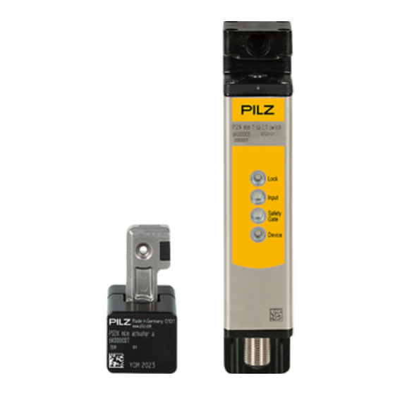
- Page 1 PSENmlock mini PSEN mlm 1 sa 1.1/2.1/2.2 Operating Manual-1005802-EN-02-Draft - PSEN sensor technology...
- Page 2 We do assure you that all persons are regarded without discrim- ination and on an equal basis. All rights to this documentation are reserved by Pilz GmbH & Co. KG. Copies may be made for the user's internal purposes. Suggestions and comments for improving this documenta- tion will be gratefully received.
-
Page 3: Table Of Contents
Pin assignment, connector and cable ..................28 EMC requirements and electrical safety ...................29 Connection to control systems and evaluation devices ............30 Important information ........................30 Minimum requirements for activation of guard locking..............31 Single connection........................33 Operating Manual PSENmlock mini, PSEN mlm 1 sa 1.1/2.1/2.2 1005802-EN-02-Draft... - Page 4 Safety characteristic data ......................72 Supplementary data .......................73 16.1 Radio approval ..........................73 Order reference ........................74 17.1 System ............................74 17.2 Accessories..........................75 EC declaration of conformity ....................78 EC declaration of conformity ....................79 UKCA-Declaration of Conformity ..................80 Operating Manual PSENmlock mini, PSEN mlm 1 sa 1.1/2.1/2.2 1005802-EN-02-Draft...
-
Page 5: Introduction
This describes a situation in which the product or devices could be dam- aged and also provides information on preventive measures that can be taken. It also highlights areas within the text that are of particular import- ance. Operating Manual PSENmlock mini, PSEN mlm 1 sa 1.1/2.1/2.2 1005802-EN-02-Draft... -
Page 6: Third-Party Manufacturer Licence Information
This product includes Open Source software with various licenses. Further information is available in the document "Third-party manufacturer licence informa- tion PSEN mlm 1 ba/sa" (document number 1006757) at www.pilz.com. Operating Manual PSENmlock mini, PSEN mlm 1 sa 1.1/2.1/2.2 1005802-EN-02-Draft... -
Page 7: Safety
Intended use PSENmlock mini is used for safe guard locking and safe interlocking on small swing gates and sliding gates, as well as flaps and covers. It prevents a safeguard from being opened while a hazardous machine function is being performed. -
Page 8: Safety Regulations
Are familiar with the basic regulations concerning health and safety / accident prevention, Have read and understood the information provided in the section entitled Safety Have a good knowledge of the generic and specialist standards applicable to the specific application. Operating Manual PSENmlock mini, PSEN mlm 1 sa 1.1/2.1/2.2 1005802-EN-02-Draft... -
Page 9: Warranty And Liability
– You should prevent the interlocking and guard locking system from being manipulated with an inappropriate actuator. – Keep the substitute actuator (optional) in a safe place and protect it from unauthorised access. – Destroy any replaced actuators before disposal. Operating Manual PSENmlock mini, PSEN mlm 1 sa 1.1/2.1/2.2 1005802-EN-02-Draft... -
Page 10: Security
Perform a risk assessment in accordance with VDI/VDE 2182 or IEC 62443-3-2 and plan the security measures with care. If necessary, seek advice from Pilz Customer Support. Operating Manual PSENmlock mini, PSEN mlm 1 sa 1.1/2.1/2.2 | 10... -
Page 11: Overview
Guard locking element keeps the safety gate from being opened unintentionally Auxiliary release for opening the safety gate Suitable for left and right hinged safety gates Pilz coding type Information about the Pilz coding types can be found under Teaching in the actuator [ 39]. -
Page 12: Approved Combinations
Safety switch Actuator PSEN mlm x sa 2.1 switch PSEN mlm actuator a PSEN mlm actuator b PSEN mlm x sa 2.2 switch PSEN mlm actuator a PSEN mlm actuator b Operating Manual PSENmlock mini, PSEN mlm 1 sa 1.1/2.1/2.2 | 12 1005802-EN-02-Draft... -
Page 13: Function Description
Safety switch and actuator a (left-hand side mounting, external attachment) Gate open Safety switch and actuator a (left-hand side mounting, external attachment) Gate closed Actuator a Safety switch Operating Manual PSENmlock mini, PSEN mlm 1 sa 1.1/2.1/2.2 | 13 1005802-EN-02-Draft... - Page 14 Safety switch and actuator b, internal attachment Legend Safety switch and actuator b (front mounting, internal attachment) Gate closed Safety switch and actuator b (front mounting, internal attachment) Gate open Actuator b Safety switch Operating Manual PSENmlock mini, PSEN mlm 1 sa 1.1/2.1/2.2 | 14 1005802-EN-02-Draft...
-
Page 15: Safety Outputs 12 And 22
12/22 switch off (low) and the Input LED goes out. If this safety input switches back from low to high while the other safety input remains high, safety outputs 12/22 switch to high. Operating Manual PSENmlock mini, PSEN mlm 1 sa 1.1/2.1/2.2 | 15 1005802-EN-02-Draft... -
Page 16: Safety Inputs S11 And S21 (Series Connection)
– Guard locking remains activated, if it was activated prior to the power interruption. Guard locking may only be deactivated by the higher level safety controller once the haz- ardous machine movement has been completed. Operating Manual PSENmlock mini, PSEN mlm 1 sa 1.1/2.1/2.2 | 16 1005802-EN-02-Draft... - Page 17 PSEN cable M12-8sf M12-8sm (order number depends on the cable length) 8-core cable PSEN cable M12-8sf (order number depends on the cable length) Series connection for diagnostics with Safety Device Diagnostics Operating Manual PSENmlock mini, PSEN mlm 1 sa 1.1/2.1/2.2 | 17 1005802-EN-02-Draft...
-
Page 18: Safety Device Diagnostics
– Read the sensors’ configuration parameters (examples: number of teach-in pro- cesses remaining, switch’s serial number) Operating Manual PSENmlock mini, PSEN mlm 1 sa 1.1/2.1/2.2 | 18 1005802-EN-02-Draft... - Page 19 75]) to connect several sensors with only one cable from the field in the control cabinet. Further information on Safety Device Diagnostics can be found in Additional documents that apply [ Operating Manual PSENmlock mini, PSEN mlm 1 sa 1.1/2.1/2.2 | 19 1005802-EN-02-Draft...
-
Page 20: Operating Modes
S31/S41 (S31/S41 must have a high signal). The safety requirements are guaranteed by the signals at safety inputs S31/S41 (the fieldbus for Safety Device Diagnostics communication is not safety-related). Operating Manual PSENmlock mini, PSEN mlm 1 sa 1.1/2.1/2.2 | 20 1005802-EN-02-Draft... -
Page 21: Operation Without Safety Device Diagnostics
Series connection input switches to high Safety gate closed Guard locking requested (by safety controller) The safety gate is securely locked (guard locking is activated) Execution of the hazardous machine function is permitted Operating Manual PSENmlock mini, PSEN mlm 1 sa 1.1/2.1/2.2 | 21 1005802-EN-02-Draft... -
Page 22: Timing Diagram, Case 2 (Automatic Guard Locking When Closing The Safety Gate)
Guard locking is activated automatically when closing the gate (power to unlock) The safety gate is securely locked (guard locking is activated) Execution of the hazardous machine function is permitted Operating Manual PSENmlock mini, PSEN mlm 1 sa 1.1/2.1/2.2 | 22 1005802-EN-02-Draft... -
Page 23: Operation With Active Use Of Safety Diagnostics
Deactivation of guard locking is requested (by safety controller) Guard locking is deactivated via SDD guard locking command (not safety-related) Safety gate open Safety gate guard locking requested (by safety controller) Operating Manual PSENmlock mini, PSEN mlm 1 sa 1.1/2.1/2.2 | 23 1005802-EN-02-Draft... -
Page 24: Block Diagram
Actuator RFID Fig.: Legend Supply Voltage A1: +24 V A2: 0 V [S31], [S41] Safety inputs Activation of solenoid to open and close guard locking [Y1] Diagnostic input Operating Manual PSENmlock mini, PSEN mlm 1 sa 1.1/2.1/2.2 | 24 1005802-EN-02-Draft... -
Page 25: Auxiliary Release
12 and 22. A warning will be output (see chapter Operation [ 56]). The safety switch does not switch to the fault condi- tion. It is possible to open guard locking using the control system. Operating Manual PSENmlock mini, PSEN mlm 1 sa 1.1/2.1/2.2 | 25 1005802-EN-02-Draft... -
Page 26: Recommissioning
3. Carry out a function test on the safety switch and actuator. The safety function may only be checked by qualified personnel. INFORMATION If the auxiliary release screw is not turned back correctly after use, guard locking cannot be activated/deactivated. Operating Manual PSENmlock mini, PSEN mlm 1 sa 1.1/2.1/2.2 | 26 1005802-EN-02-Draft... - Page 27 Function description NOTICE Once the auxiliary release has been operated, guard locking cannot be re- activated until the safety gates are opened and then closed again. Operating Manual PSENmlock mini, PSEN mlm 1 sa 1.1/2.1/2.2 | 27 1005802-EN-02-Draft...
-
Page 28: Wiring
Safety input channel 1 Black Signal output/diagnostic Grey output Diagnostics input Safety input channel 2 Purple Operation of solenoid of the Grey-pink next safety switch in the series connection (channel Operating Manual PSENmlock mini, PSEN mlm 1 sa 1.1/2.1/2.2 | 28 1005802-EN-02-Draft... -
Page 29: Emc Requirements And Electrical Safety
Only use safety relays with a 24 VDC supply voltage. Safety relays with a wide-range power supply or in AC device versions have internal potential isolation and are not suitable as evaluation devices. Operating Manual PSENmlock mini, PSEN mlm 1 sa 1.1/2.1/2.2 | 29 1005802-EN-02-Draft... -
Page 30: Connection To Control Systems And Evaluation Devices
– Use an evaluation device/safety system to test whether the plant is in a safe condition. – Do not operate the solenoid via S31/S41 unless the plant is in a safe condition. Operating Manual PSENmlock mini, PSEN mlm 1 sa 1.1/2.1/2.2 | 30 1005802-EN-02-Draft... -
Page 31: Minimum Requirements For Activation Of Guard Locking
PL d (Cat. 3) applications Use 2-channel operation for safety inputs S31 and S41 (solenoid activation) Use 2-channel processing for safety outputs (12 and 22) Operating Manual PSENmlock mini, PSEN mlm 1 sa 1.1/2.1/2.2 | 31 1005802-EN-02-Draft... - Page 32 Use 1-channel operation for interconnected safety inputs S31 and S41 (solenoid activa- tion) Exclusion of shorts across signal cables through appropriate measures (e.g. protected cable layout, see EN ISO 13849-2) Operating Manual PSENmlock mini, PSEN mlm 1 sa 1.1/2.1/2.2 | 32 1005802-EN-02-Draft...
-
Page 33: Single Connection
When several (n) devices are connected in series, the input current is multi- plied by the number of safety switches connected in series (see Technical details [ 63]). Operating Manual PSENmlock mini, PSEN mlm 1 sa 1.1/2.1/2.2 | 33 1005802-EN-02-Draft... - Page 34 Series connection of 1 to 8 safety switches Supply voltage at the safety controller = Supply voltage at the safety controller = 24.0 V 28.8 V Total cable length: 45 m Total cable length: 75 m Operating Manual PSENmlock mini, PSEN mlm 1 sa 1.1/2.1/2.2 | 34 1005802-EN-02-Draft...
- Page 35 This reduction can be avoided by installing a diode when connecting S41 in the control cabinet (see Minimum requirements for activation of guard locking [ 31], "Use in PL d (Cat. 2) applications"). Operating Manual PSENmlock mini, PSEN mlm 1 sa 1.1/2.1/2.2 | 35 1005802-EN-02-Draft...
- Page 36 Connecting the safety switches in a series connection 24 V 0 V Safety switch Actuator Safety switch Actuator Actuator Safety switch Safety control system FS: Failsafe Fieldbus module Operating Manual PSENmlock mini, PSEN mlm 1 sa 1.1/2.1/2.2 | 36 1005802-EN-02-Draft...
- Page 37 – Connect a 12-core cable (for example PSEN cable M12-12sf M12-12sm) to the safety switch and guide it to the terminal block in the control cabinet. NOTICE Before commissioning, check the Series connection of the safety channels [ 59]. Operating Manual PSENmlock mini, PSEN mlm 1 sa 1.1/2.1/2.2 | 37 1005802-EN-02-Draft...
-
Page 38: Connection To Pilz Evaluation Devices
Connection to control systems and evaluation devices Connection to Pilz evaluation devices The safety switch can be connected to Pilz evaluation devices. Suitable Pilz evaluation devices are, for example: PNOZmulti for safety gate monitoring Configure the switch in the PNOZmulti Configurator with switch type 3. -
Page 39: Teaching In The Actuator
Teaching in the actuator Teaching in the actuator A distinction is made between the following Pilz coding types: Coded The safety switch PSEN mlm x sa 1.1 switch accepts any PSEN mlm actuator. Fully-coded The safety switch PSEN mlm x sa 2.1 switch accepts only one PSEN mlm actuator. - Page 40 The safety gate LEDs light up a constant yellow when the actuator is detected (see Normal operation [ 56]). NOTICE No other actuator may be taught in once this actuator has been taught. Operating Manual PSENmlock mini, PSEN mlm 1 sa 1.1/2.1/2.2 | 40 1005802-EN-02-Draft...
-
Page 41: Installation
Don’t fully tighten the safety screws until the safety switches and actuators are correctly aligned and the function has been tested. If possible, conceal the installation of the safety switch and actuator. Operating Manual PSENmlock mini, PSEN mlm 1 sa 1.1/2.1/2.2 | 41 1005802-EN-02-Draft... -
Page 42: Align Safety Switch And Actuator
Fig.: Align safety switch and actuator Comply with the stated dimensions, tolerances, see Technical details [ 63]. A steel square is helpful for aligning the safety switch and actuator. Operating Manual PSENmlock mini, PSEN mlm 1 sa 1.1/2.1/2.2 | 42 1005802-EN-02-Draft... -
Page 43: Installation Of Multiple Safety Switches
Fig.: Distances, safety switches in parallel > 35 mm Fig.: Distances, safety switches directly in parallel, with vertical offset > 35 mm Fig.: Distances, safety switches "head to head", no distance Operating Manual PSENmlock mini, PSEN mlm 1 sa 1.1/2.1/2.2 | 43 1005802-EN-02-Draft... -
Page 44: Psen Mlm Mounting Types
Installation PSEN mlm mounting types The PSENmlock mini can be mounted as an internal or external attachment. External at- tachment is the preferred mounting type. 9.4.1 External attachment with actuator a The following mounting examples are based on a 30 x 30 mm profile. With other profiles, mounting plates are required for safety switches and actuators. - Page 45 Use two 30 mm M5 cylinder head screws to attach the actuator to the gate. The actuator should engage smoothly into the safety switch. Maintain a slight parallel offset from the gate’s rotation point when installing the actuator. Operating Manual PSENmlock mini, PSEN mlm 1 sa 1.1/2.1/2.2 | 45 1005802-EN-02-Draft...
- Page 46 The insertion of the actuator into the safety switch is influenced by the above factors. For this reason we recommend you use 3D data to inspect the installation situation, see www.pilz.com. Operating Manual PSENmlock mini, PSEN mlm 1 sa 1.1/2.1/2.2 | 46 1005802-EN-02-Draft...
- Page 47 Installation Mount safety switch on a swing gate across the rotational axis Depending on the installation boundary conditions, a larger gate radius may be required. Operating Manual PSENmlock mini, PSEN mlm 1 sa 1.1/2.1/2.2 | 47 1005802-EN-02-Draft...
-
Page 48: Internal Attachment With Actuator B
Gate profile 30 x 30 mm Legend Gate radius R X-dimension Handle on the outside Factors that positively influence the smooth insertion of the actuator into the safety switch: Small X-dimension Operating Manual PSENmlock mini, PSEN mlm 1 sa 1.1/2.1/2.2 | 48 1005802-EN-02-Draft... - Page 49 On the safety switch, ensure that the auxiliary release screw is reachable with an Allen key (SW4) on one of the two sides when the gate/cover/flap is closed. Operating Manual PSENmlock mini, PSEN mlm 1 sa 1.1/2.1/2.2 | 49 1005802-EN-02-Draft...
-
Page 50: Installation Safety Switch
Order reference: Accessories. Different holding forces arise, based on the installation. Fig.: Holding force directions Holding force F in Z-direction: 1500 N Holding force F in X-direction: 1950 N Operating Manual PSENmlock mini, PSEN mlm 1 sa 1.1/2.1/2.2 | 50 1005802-EN-02-Draft... -
Page 51: Mounting Of Safety Switch Using Two Screws
Provide the mounting surface with tapped holes as indicated. 1. Attach the safety switch to the swing gate/sliding gate/flap/cover. 2. Use two M5 screws to fix the safety switch to the mounting surface. Operating Manual PSENmlock mini, PSEN mlm 1 sa 1.1/2.1/2.2 | 51 1005802-EN-02-Draft... -
Page 52: Actuator Installation
6K000021, is suitable for internal attachment of the safety switch parallel to the rotational axis. M5 screws 1 x M5 one-way screw (optional) for mounting the actuator PSEN mlm mounting set 1 (material number 6K000021) Operating Manual PSENmlock mini, PSEN mlm 1 sa 1.1/2.1/2.2 | 52 1005802-EN-02-Draft... - Page 53 Mounting plate for actuator b Actuator b (mounting using 2 screws, a one-way screw optional) Safety switch Bracket for safety switch (Mounting using 2 screws) [1] [4] PSEN mlm mounting set 1 (material number 6K000021) Operating Manual PSENmlock mini, PSEN mlm 1 sa 1.1/2.1/2.2 | 53 1005802-EN-02-Draft...
- Page 54 Hole for screw connection to 30 mm profile Hole for screw connection to 45 mm profile For 30/40 mm profile Elongated hole for screw connection to universal profiles Operating Manual PSENmlock mini, PSEN mlm 1 sa 1.1/2.1/2.2 | 54 1005802-EN-02-Draft...
-
Page 55: Mounting Guidelines For Internally Attached Auxiliary Release
Fig.: Internally attached auxiliary release reachable with an Allen key (SW4|) via a suitable opening (ca. 57) Fig.: Dimensions for reaching the auxiliary release Legend Allen key (SW4) Operating Manual PSENmlock mini, PSEN mlm 1 sa 1.1/2.1/2.2 | 55 1005802-EN-02-Draft... -
Page 56: Operation
S11 and S21 are low Green Safety gate open, actuator not de- tected, guard locking deactivated, safety inputs S11 and S21 are high Green Yel- Operating Manual PSENmlock mini, PSEN mlm 1 sa 1.1/2.1/2.2 | 56 1005802-EN-02-Draft... - Page 57 Auxiliary release Auxiliary re- itive play lease: Turn back the auxili- defin- Green ary release itive screw and then recommission the safety switch (see Recommissioni ng [ 26]) Operating Manual PSENmlock mini, PSEN mlm 1 sa 1.1/2.1/2.2 | 57 1005802-EN-02-Draft...
-
Page 58: Fault Indicator Psen Mlm
Recommissioning [ 26]). Device is in error Change the safety switch. state. Wrong actuator Only use approved combinations Dis- (see Approved play combinations [ 12]) Green Yellow defin- itive Operating Manual PSENmlock mini, PSEN mlm 1 sa 1.1/2.1/2.2 | 58 1005802-EN-02-Draft... -
Page 59: Checks And Maintenance
Before commissioning and after each change, check that the safety function is guaranteed when the gates are opened. To do this, open each gate individually and check the status at the inputs on the evaluation device: Close all the gates. Operating Manual PSENmlock mini, PSEN mlm 1 sa 1.1/2.1/2.2 | 59 1005802-EN-02-Draft... - Page 60 High signals must return at the inputs on the evaluation device (e.g. S11, S21 or I1, I2). Repeat the test for each gate. If the input signals do not react as described above, check and rectify the wiring and carry out the test again. Operating Manual PSENmlock mini, PSEN mlm 1 sa 1.1/2.1/2.2 | 60 1005802-EN-02-Draft...
-
Page 61: Dimensions
Dimensions Dimensions Safety switch PSEN mlm x ba/sa 1.1/2.1/2.2 30.4 16.2 30.4 15.2 (13.2) 15.2 Fig.: Safety switch Operating Manual PSENmlock mini, PSEN mlm 1 sa 1.1/2.1/2.2 | 61 1005802-EN-02-Draft... - Page 62 Dimensions Actuator a, PSEN mlm 1.1/2.1/2.2 58.5 48.5 Fig.: Actuator a Actuator b, PSEN mlm 1.1/2.1/2.2 Fig.: Actuator b Operating Manual PSENmlock mini, PSEN mlm 1 sa 1.1/2.1/2.2 | 62 1005802-EN-02-Draft...
-
Page 63: Technical Details
24 V DC Current at solenoid input 4 mA 4 mA 4 mA Input current range 2 - 2,6 mA 2 - 2,6 mA 2 - 2,6 mA Operating Manual PSENmlock mini, PSEN mlm 1 sa 1.1/2.1/2.2 | 63 1005802-EN-02-Draft... - Page 64 -10 - 60 °C Storage temperature in accordance with the standard EN 60068-2-1/-2 EN 60068-2-1/-2 EN 60068-2-1/-2 Temperature range -25 - 70 °C -25 - 70 °C -25 - 70 °C Operating Manual PSENmlock mini, PSEN mlm 1 sa 1.1/2.1/2.2 | 64 1005802-EN-02-Draft...
- Page 65 +/- 1,0 mm Max. angular offset around the X axis +/-3,1 deg +/-3,1 deg +/-3,1 deg Max. angular offset around the Y axis -5/+12 deg -5/+12 deg -5/+12 deg Operating Manual PSENmlock mini, PSEN mlm 1 sa 1.1/2.1/2.2 | 65 1005802-EN-02-Draft...
- Page 66 6K000019 6K000020 Frequency band 127 kHz +/- 3 kHz 127 kHz +/- 3 kHz 127 kHz +/- 3 kHz Max. transmitter output 15 mW 15 mW 15 mW Operating Manual PSENmlock mini, PSEN mlm 1 sa 1.1/2.1/2.2 | 66 1005802-EN-02-Draft...
- Page 67 Voltage drop at OSSDs 1,25 V 1,25 V 1,25 V Conditional rated short cir- cuit current 100 A 100 A 100 A Lowest operating current 1 mA 1 mA 1 mA Operating Manual PSENmlock mini, PSEN mlm 1 sa 1.1/2.1/2.2 | 67 1005802-EN-02-Draft...
- Page 68 EN 60947-5-2 EN 60947-5-2 EN 60947-5-2 Frequency 10 - 55 Hz 10 - 55 Hz 10 - 55 Hz Amplitude 1 mm 1 mm 1 mm Operating Manual PSENmlock mini, PSEN mlm 1 sa 1.1/2.1/2.2 | 68 1005802-EN-02-Draft...
- Page 69 45 m 45 m Material Stainless steel, plastic, Stainless steel, plastic, Stainless steel, plastic, galvanised steel, die galvanised steel, die galvanised steel, die cast zinc cast zinc cast zinc Operating Manual PSENmlock mini, PSEN mlm 1 sa 1.1/2.1/2.2 | 69 1005802-EN-02-Draft...
- Page 70 425 g Weight of actuator 170 g 170 g 170 g Weight 595 g 595 g 595 g Where standards are undated, the 2023-08 latest editions shall apply. Operating Manual PSENmlock mini, PSEN mlm 1 sa 1.1/2.1/2.2 | 70 1005802-EN-02-Draft...
-
Page 71: Classification In Accordance With Zvei, Cb24I
Safe 1-pole SC outputs Source Drain Safety switch Evaluation device Parameter source Min. Typ. Max. test pulse duration 450 µs Max. ratio t Rated current 0,1 A Capacitive load 70 nF Operating Manual PSENmlock mini, PSEN mlm 1 sa 1.1/2.1/2.2 | 71 1005802-EN-02-Draft... -
Page 72: Safety Characteristic Data
NOTICE Be sure that you observe the mechanical life. The safety characteristic data are only valid as long as the values of mechanical life are met. Operating Manual PSENmlock mini, PSEN mlm 1 sa 1.1/2.1/2.2 | 72 1005802-EN-02-Draft... -
Page 73: Supplementary Data
2) this product must accept any interference received, including interference that may cause undesired operation. Changes or modifications made to this product not expressly approved by Pilz may void the FCC authorization to operate this equipment. NOTE: This equipment has been tested and found to comply with the limits for a Class A digital device, pursuant to Part 15 of the FCC Rules. -
Page 74: Order Reference
12-pin M12 male connector, series connec- tion, automatic reset Operating Manual PSENmlock mini, PSEN mlm 1 sa 1.1/2.1/2.2 | 74 1005802-EN-02-Draft... -
Page 75: Accessories
12-pin M12 male connector, series connection, automatic reset PSEN mlm actu- Actuator a, for safety guard locking device PSENmlock mini, side 6K000007 ator a mounting, external attachment... - Page 76 M12-12sm 3m nector, straight nector, straight PSEN cable M12, 12-pin fe- M12, 12-pin 570360 M12-12sf/ male con- male con- M12-12sm 5m nector, straight nector, straight Operating Manual PSENmlock mini, PSEN mlm 1 sa 1.1/2.1/2.2 | 76 1005802-EN-02-Draft...
- Page 77 M12, 8-pin fe- M12, 12-pin fe- 570486 male connector male connector male connector PSEN ml end ad- M12, 12-pin fe- M12, 8-pin 570487 apter male connector male connector Operating Manual PSENmlock mini, PSEN mlm 1 sa 1.1/2.1/2.2 | 77 1005802-EN-02-Draft...
-
Page 78: Ec Declaration Of Conformity
European Parliament and of the Council. The complete EC Declaration of Conformity is available on the Internet at www.pilz.com/downloads. Representative: Pilz GmbH & Co. KG, Felix-Wankel-Str. 2, 73760 Ostfildern, Germany Operating Manual PSENmlock mini, PSEN mlm 1 sa 1.1/2.1/2.2... -
Page 79: Ec Declaration Of Conformity
2014/53/EU on radio equipment The complete EC Declaration of Conformity is available on the Internet at www.pilz.com/downloads. Representative: Pilz GmbH & Co. KG, Felix-Wankel-Str. 2, 73760 Ostfildern, Germany Operating Manual PSENmlock mini, PSEN mlm 1 sa 1.1/2.1/2.2 | 79 1005802-EN-02-Draft... -
Page 80: Ukca-Declaration Of Conformity
The complete UKCA Declaration of Conformity is available on the Internet at www.pilz.com/ downloads. Representative: Pilz Automation Technology, Pilz House, Little Colliers Field, Corby, Northamptonshire, NN18 8TJ United Kingdom, eMail: mail@pilz.co.uk Operating Manual PSENmlock mini, PSEN mlm 1 sa 1.1/2.1/2.2 | 80 1005802-EN-02-Draft... - Page 81 We are represented internationally. Please refer to our homepage www.pilz.com for further details or contact our headquarters. Headquarters: Pilz GmbH & Co. KG, Felix-Wankel-Straße 2, 73760 Ostfildern, Germany Telephone: +49 711 3409-0, E-Mail: info@pilz.com, Internet: www.pilz.com...
Need help?
Do you have a question about the PSENmlock mini and is the answer not in the manual?
Questions and answers