Download Print this page

Advertisement

Quick Links

21904-3FR-03
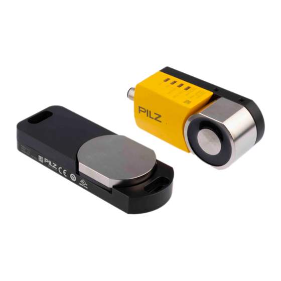
PSEN sl-0.5p
PSEN sl-0.5p
21904-3FR-03
Sicheres Schutztürsystem PSENslock
Das sichere Schutztürsystem erfüllt die Anfor-
1153871755
derungen nach
EN 60204-1
EN 60947-5-3: PDF-M zusammen mit dem
Betätiger (siehe Technische Daten).
EN 62061: SIL CL 3
EN ISO 13849-1. PL e und Kat. 4
Der Sicherheitsschalter darf nur mit dem zu-
gehörigen Betätiger verwendet werden (sie-
he Technische Daten).
Die Sicherheitsausgänge müssen 2-kanalig
weiterverarbeitet werden.
Zu Ihrer Sicherheit
Installieren und nehmen Sie das Gerät nur
547263243
dann in Betrieb, wenn Sie diese Betriebsan-
leitung gelesen und verstanden haben und
Sie mit den geltenden Vorschriften über Ar-
beitssicherheit und Unfallverhütung vertraut
sind.
Beachten Sie die VDE- sowie die örtlichen
Vorschriften, insbesondere hinsichtlich
Schutzmaßnahmen
Durch Öffnen des Gehäuses oder eigen-
mächtige Umbauten erlischt jegliche Ge-
währleistung.
Entfernen Sie die Schutzkappe erst unmittel-
777809547
bar vor Anschluss des Geräts.
1007068171
Wichtig!
Die Magnetoberfläche und die Gegenplatte
können sich erwärmen. Achten Sie bei der
Montage darauf, dass die Wärmeabfuhr ge-
währleistet ist.
Gerätemerkmale
Transpondertechnik
1013887115
Gerätevarianten:
1153877387
– PSEN sl-0.5p 1.1: codiert
– PSEN sl-0.5p 2.1: vollcodiert
– PSEN sl-0.5p 2.2: unikat codiert
1013941387
Zweikanaliger Betrieb
2 Sicherheitsausgänge
2 Eingänge für Reihenschaltung
1 Meldeausgang
Magnetische Zuhaltung für Prozessschutz
1 Eingang zum Ein-/Ausschalten des Zuhal-
temagnets
LED-Anzeige für
– Versorgungsspannung/Fehler
– Tür geschlossen
– Zustand Eingänge
– Zustand magnetische Zuhaltung
8-poliger M12-Anschlussstecker
PSENslock safety gate system
The safety gate system meets the requirements
in accordance with
EN 60204-1
EN 60947-5-3: PDF-M in conjunction with
the actuator (see Technical Details).
EN 62061: SIL CL 3
EN ISO 13849-1. PL e and Cat. 4
The safety switch may only be used with the
corresponding actuator (see Technical De-
tails).
The safety outputs must use 2-channel
processing.
For your safety
Only install and commission the unit if you
have read and understood these operating
instructions and are familiar with the applica-
ble regulations for health and safety at work
and accident prevention.
Ensure VDE and local regulations are met,
especially those relating to safety.
Any guarantee is rendered invalid if the hous-
ing is opened or unauthorised modifications
are carried out.
Do not remove the protective cap until you
are just about to connect the unit.
Notice!
The magnet surface and counterplate may
heat up. When installing, make sure that
heat dissipation is guaranteed.
Unit features
Transponder technology
Unit types:
– PSEN sl-0.5p 1.1: Coded
– PSEN sl-0.5p 2.1: Fully coded
– PSEN sl-0.5p 2.2: Uniquely coded
Dual-channel operation
2 safety outputs
2 inputs for series connection
1 signal output
Magnetic guard locking for process protec-
tion
1 input to switch the locking magnet on/off
LEDs for
– Supply voltage/fault
– Gate closed
– Status of the inputs
– Status of the magnetic guard locking de-
vice
8-pin M12 connector
- 1 -
Système de sécurité pour protecteurs
mobiles PSENslock
Le système de sécurité pour protecteurs mobi-
les satisfait aux exigences des normes
EN 60204-1
EN 60947-5-3 : PDF-M avec l'actionneur
(voir les caractéristiques techniques).
EN 62061 : SIL CL 3
EN ISO 13849-1. PL e et cat. 4
Le capteur de sécurité doit être utilisé uni-
quement avec l'actionneur correspondant
(voir les caractéristiques techniques).
Les sorties de sécurité doivent être traitées par
2 canaux.
Pour votre sécurité
Vous n'installerez l'appareil et ne le mettrez
en service qu'après avoir lu et compris le
présent manuel d'utilisation et vous être fa-
miliarisé avec les prescriptions en vigueur
sur la sécurité du travail et la prévention des
accidents.
Respectez les normes locales ou VDE, parti-
culièrement en ce qui concerne la sécurité.
L'ouverture de l'appareil ou sa modification
annule automatiquement la garantie.
Veuillez retirer le cache de protection avant
de raccorder l'appareil.
Important !
La surface magnétique et la contreplaque
peuvent chauffer. Pour le montage, faites at-
tention à ce que l'évacuation de la chaleur
soit assurée.
Caractéristiques de l'appareil
Technique à transpondeur
Modèles d'appareils :
– PSEN sl-0.5p 1.1 : codé
– PSEN sl-0.5p 2.1 : codé multiple
– PSEN sl-0.5p 2.2 : codé unique
Commande par 2 canaux
2 sorties de sécurité
2 entrées pour montage en série
1 sortie de signalisation
Interverrouillage magnétique pour protéger
les process
1 entrée pour l'activation / la désactivation
de l'aimant d'interverrouillage
LED de visualisation pour
– tension d'alimentation / défauts
– protecteur mobile fermé
– état des entrées
– état de l'interverrouillage magnétique
connecteur M12 à 8 broches

Advertisement

loading

Summary of Contents for Pilz PSENslock Series

  • Page 1 21904-3FR-03 PSEN sl-0.5p 21904-3FR-03 PSEN sl-0.5p Sicheres Schutztürsystem PSENslock PSENslock safety gate system Système de sécurité pour protecteurs 1153871755 Das sichere Schutztürsystem erfüllt die Anfor- The safety gate system meets the requirements mobiles PSENslock derungen nach in accordance with Le système de sécurité pour protecteurs mobi- EN 60204-1 EN 60204-1 les satisfait aux exigences des normes...
  • Page 2 Blockschaltbild Block diagram Schéma de principe Funktionsbeschreibung Function description Description du fonctionnement 1090037387 An den Sicherheitsausgängen 12 und 22 liegt There is a high signal at safety output 12 and 22 Un niveau haut est généré sur les sorties de sé- ein High-Signal, wenn gleichzeitig: if the following occur simultaneously: curité...
  • Page 3 Funktion/ Klemmenbezeichnung/ Adernfarbe (Pilz Kabel)/ Broche Function/ Terminal designation/ Cable colour (Cable Pilz)/ Foncion Désignation des bornes Couleur du fil (fil de Pilz) Eingang Kanal 2/ weiß/white/blanc Input, channel 2/ Canal d'entrée 2 +24 UB braun/brown/marron Ausgang Kanal 1/ grün/green/vert...
  • Page 4 Anschluss an Auswertegeräte Connection to evaluation devices Raccordement aux appareils de contrôle 1104750091 Bitte beachten Sie: Please note: Tenez compte de ce qui suit : das Netzteil muss den Vorschriften für Klein- The power supply must meet the regulations Cette alimentation doit être conforme aux spannungen mit sicherer Trennung (SELV, for extra low voltages with safe separation prescriptions relatives aux basses tensions à...
  • Page 5 Reihenschaltung Series connection Montage en série 1022409355 ACHTUNG! CAUTION! ATTENTION ! Bei Reihenschaltung mehrerer Geräte ad- When several units are connected in series, Si plusieurs appareils sont montés en série, diert sich die Rückfallverzögerung mit der the delay-on de-energisation time increas- la temporisation à...
  • Page 6 Anschluss an PNOZ X, PNOZpower, PNOZ- Connection to PNOZ X, PNOZpower, Raccordement aux PNOZ X, PNOZpower, sigma, PNOZelog PNOZsigma, PNOZelog PNOZsigma, PNOZelog - 6 -...
  • Page 7 Anschluss an PNOZmulti Connection to PNOZmulti Raccordement au PNOZmulti Anschluss an PSS Connection to PSS Raccordement au PSS - 7 -...
  • Page 8 PSEN sl-0.5p 1.1 PSEN sl-0.5p 1.1 PSEN sl-0.5p 1.1 1175993995 Es wird jeder zugehörige Betätiger von Pilz (sie- Any corresponding Pilz actuator (see Technical Chaque actionneur de Pilz (voir les caractéristi- he Technische Daten) erkannt, sobald er in den Details) is detected as soon as it is brought into ques techniques) est détecté...
  • Page 9 An Schwenktüre montieren Installing at swing gate Montage sur porte à battants 1059870603 1. Betätiger auf gewünschte Höhe an Tür- 1. Align actuator with gate edge at the re- 1. Aligner l'actionneur sur le bord de la porte kante bündig ausrichten und Schrauben quired height and tighten screws.
  • Page 10 An Schiebetüre montieren Installing at sliding gate Montage sur porte coulissante 1048678411 1. Montagewinkel für Betätiger an Schiebe- 1. Align mounting bracket for actuator at the 1. Aligner l'équerre de montage de l'action- türe bündig ausrichten und Schrauben fest- sliding gate and tighten screws. neur sur le bord de la porte coulissante et ziehen.
  • Page 11 Betrieb Operation Fonctionnement Prüfen Sie vor der Inbetriebnahme die Funk- Check the function of the safety switch be- Avant la mise en service, veuillez vérifer la 800695819 tion des Sicherheitsschalters. fore commissioning. fonction du capteur de sécurité. ACHTUNG! CAUTION! ATTENTION ! Verschmutzte Oberflächen können die Contaminated surfaces can reduce the Les surfaces encrassées peuvent rédui-...
  • Page 12 Abmessungen Dimensions Dimensions Sicherheitsschalter und Magnet/Safety switch and magnet Betätiger/Actuator/Actuator Capteur de sécurité et l'aimant M5 (2x) M5 (6x) Montagewinkel Schwenktüre/Mounting bracket swing gate/Equerre de montage porte à battants 11,5 54,5 Montagewinkel Schiebetüre/Mounting bracket sliding gate/Equerre de montage porte coulissante - 12 -...
  • Page 13 Technische Daten Technical details Caractéristiques techniques Elektrische Daten Electrical data Données électriques Versorgungsspannung U Supply voltage U Tension d'alimentation U 24 V Spannungstoleranz Voltage tolerance Plage de la tension d'alimentation -15 %/+10 % Leistungsaufnahme bei U Power consumption at U Consommation U 4,8 W Max.
  • Page 14 Mechanische Daten Mechanical data Données mécaniques Gesicherter Schaltabstand S Assured operating distance S Distance de commutation de sécu- 1,0 mm rité S Gesicherter Ausschaltabstand S Assured release distance S Distance de déclenchement de sé- 8 mm curité S Typischer Schaltabstand S Typical switching distance S Distance de commutation caracté- 2,0 mm...
  • Page 15 Bevollmächtigter: Norbert Fröhlich, Pilz GmbH Authorised representative: Norbert Fröhlich, Représentant : Norbert Fröhlich, Pilz GmbH & & Co. KG, Felix-Wankel-Str. 2, 73760 Ostfil- Pilz GmbH & Co. KG, Felix-Wankel-Str. 2, Co. KG, Felix-Wankel-Str. 2, 73760 Ostfildern,...