
Related Manuals for HULALA HOME SBYL1124


Summary of Contents for HULALA HOME SBYL1124
- Page 1 ITEM NO.SBYL1124 NOTE: This brochure contains IMPORTANT safty info. Please read and keep for future reference. 01/24...
- Page 2 MAINTAINANCE AND WARNING 1.Keep furniture away from heat sources. 2.Do not clean furniture with harsh cleaner or polishes.Do not use detergents,solvents,abrasives,spray packs or leather cleaner. Use non-color mild soa with warm water to clean spills(Mix 1:10 soap to water). 3.Do not place furniture under direct sunlight,material will possibly fade over time.
-
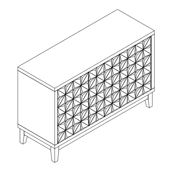
Page 3: Explosive View
EXPLOSIVE VIEW 2PERSONEN 03/24... -
Page 4: Parts List
PARTS LIST 04/24... - Page 5 PARTS LIST 05/24...
-
Page 6: Hardware List
HARDWARE LIST Ø3*15mm Ø3*15mm Ø6*50mm Ø4*25mm Ø3.5*38mm Ø3.5*20mm TOOL LIST HARDWARE SPARE LIST 06/24 Ø3*15mm Ø3*15mm Ø6*50mm Ø4*25mm... - Page 7 ASSEMBLY INSTRUCTIONS STEP-1 1.connect part #6 to part (E) with screw #1, tight screw with screwdriver #17. 2.connect part #6 to part (A) with screw #1, tight screw wit screwdriver #17. Ø3*15 07/24...
- Page 8 ASSEMBLY INSTRUCTIONS STEP-2 1.connect part (S) to part (B) with bolt #3, flat washer #7 and spring washer #8, tight bolt with allen wrench #16. 2. connect part (T) to part (B) with hand and tight it . ∅ 6*50mm 08/24...
- Page 9 ASSEMBLY INSTRUCTIONS STEP-3 1.insert part (C/D/E) to part (B), make sure all holes aligned and tight them with allen wrench #16. 09/24...
- Page 10 ASSEMBLY INSTRUCTIONS STEP-4 1.insert part(A) to part (C/D/E), make sure all holes aligned and tight them with allen wrench #16. 10/24...
- Page 11 ASSEMBLY INSTRUCTIONS STEP-5 1.connect part (F) to the unit pre-assembled at step 4 with screw #2, tight screw with screwdriver #17. ∅ 3*15mm 11/24...
- Page 12 ASSEMBLY INSTRUCTIONS STEP-6 1.connect part (L/M) to part (N) with screw #6, tight screw with screwdriver #17. 2. slide part (P) to part (L/M), make sure it also in the groove of part (N). ∅ 4*25mm 12/24...
- Page 13 ASSEMBLY INSTRUCTIONS STEP-7 1.connect part (O) to part (L/M) with part #4, tight it with screwdriver #17. 2. attach part (Q) to the drawer with hand. ∅ 4*25mm 13/24...
- Page 14 ASSEMBLY INSTRUCTIONS STEP-8 insert the drawer (O/R) to the unit pre-assembled at step7. 14/24...
- Page 15 ASSEMBLY INSTRUCTIONS STEP-9 1.Insert shelf holder #9 into the corresponding hole of panel (C)&(D)&(E) and then attach panel (H&G) to it. Shelf holder can be adjusted up or down 15/24...
- Page 16 ASSEMBLY INSTRUCTIONS STEP-10 1.connect part #10 to part (I/K) with screw #1, tight screw with screwdriver #17. 2.connect part #11 to part (J) with screw #1, tight screw with screwdriver. Ø3*15mm 16/24...
- Page 17 ASSEMBLY INSTRUCTIONS STEP-11 1.connect part (I/J/K) to the unit pre-assembled at step 10 with screw #1, tight screw with screwdriver #17. #10/#11 #17 #1 Ø3*15mm 17/24...
- Page 18 ASSEMBLY INSTRUCTIONS STEP-12 Concealed hinges are three-way adjustable: Horizontal by screw adjustment! Concealed hinges are three-way adjustable: In-and-out by loosening the hinge arm mounting screw or via cam adjustment! Concealed hinges are three-way adjustable: Vertical via slots in the mounting plate or via cam adjustment! Hinge adjustment method 18/24...
- Page 19 ASSEMBLY INSTRUCTIONS STEP-13 Attention: Before the next step, adjust the feet of the locker to keep it level. 19/24...
- Page 20 ASSEMBLY INSTRUCTIONS STEP-14 Attention: If the door looks over out or over in,you can adjust the head rebounder as image. I&J&K I&J&K 20/24...
- Page 21 ASSEMBLY INSTRUCTIONS #15 x4 Ø3*20mm STEP-15 connect part #12 to part (A) with screw #1, tight screw with screwdriver #17. 21/24...
- Page 22 ASSEMBLY INSTRUCTIONS #13 x4 Ø3.5*38mm STEP-16 Install the anti-collapse device. 2.Mark the position on the wall, that corresponds to the location of part#12 on the of panel (A); Drill and insert the expandable screw by hammer. Assemble the part #12 to the wall. Align the hole in the part #12 with the expandable screw #13 , use screw #5 to attach it and tighten by screwdriver#17.
- Page 23 ASSEMBLY INSTRUCTIONS #14 x2 STEP-17 1.Let the plastic belt #14 pass through the both part #9 and pull tightly. #14x2 #14x2 23/24...
Need help?
Do you have a question about the SBYL1124 and is the answer not in the manual?
Questions and answers