
Related Manuals for HULALA HOME SBHM0624


Summary of Contents for HULALA HOME SBHM0624
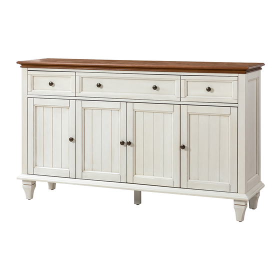
- Page 1 HULALA ITEM NO. SBHM0624 NOTE: This brochure contains IMPORTANT safty info. Please read and keep for future reference. 1/35...
- Page 2 MAINTAINANCE AND WARNING Keep furniture away from heat. Do not clean furniture with harsh cleansers or polish. Do not use detergents, Solvents, abrasives, spray packs or leather cleaner. Use non-color mild soap with warm water clean spills(Mix 1:10 soap to water) Do not place furniture under direct sunlight, material will possibly fade over time.
- Page 3 ASSEMBLY INSTRUCTIONS 3/35...
- Page 4 PARTS LIST Top panel Bottom panel Front rail Left side panel Middle vertical panel right Middle vertical panel left Right side panel Back panel 4/35...
- Page 5 PARTS LIST Middle adjustable panel Side adjustable panel Drawer front left Drawer front middle Drawer front right Drawer side left Drawer side right Drawer back side Drawer back middle Drawer bottom side 5/35...
- Page 6 PARTS LIST Left door Drawer bottom middle Middle left door Middle right door Right door Middle leg 6/35...
- Page 7 HARDWARE LIST Bolt Allen wrench Magnet ø1/4”x1-3/4”L Screw Shelf holder Knob ø3x15mm Screw bolt ø4x19mm ø8x25mm Hinge Screw Hinge ø3x15mm Bracket Screw Expansion nut ø7x35mm screwdriver 7/35...
- Page 8 SPARE Screw Screw Screw ø3x15mm ø8x25mm ø3x15mm Be sure to check all packing material carefully for small parts, which may have come loose inside the carton during shipment. 8/36...
- Page 9 ASSEMBLY INSTRUCTIONS Step 1 Attach leg(X/Y) to bottom panel(B) with bolt(1) , tight it with Allen wrench(2). 9/36...
- Page 10 ASSEMBLY INSTRUCTIONS Step 2 Attach Magnet(3) to front rail (C) with screw(4) , tight it with screwdriver(16). 10/36...
- Page 11 ASSEMBLY INSTRUCTIONS Step 3 Slide front rail(C) to middle left vertical panel(E ) and middle right vertical panel(F). 11/36...
- Page 12 ASSEMBLY INSTRUCTIONS Step 4 D&G D&G Attach left side panel(D) and right side panel(G) to preassemble unit at step 3 , and tight it with Allen wrench(2). 12/36...
- Page 13 ASSEMBLY INSTRUCTIONS Step 5 D&E&F&G D&E&F&G Attach preassemble unit at step 4 to bottom panel(B) , and tight it with Allen wrench(2). 13/36...
- Page 14 ASSEMBLY INSTRUCTIONS Step 6 D&E&F&G D&E&F&G Attach preassemble unit at step 5 to top panel(A) , and tight it with Allen wrench(2). 14/36...
- Page 15 ASSEMBLY INSTRUCTIONS Step 7 Attach back panel( H) to preassemble unit at step 6 with screw (4), tight screw with screwdriver(16). 15/36...
- Page 16 ASSEMBLY INSTRUCTIONS Step 8 shelf holder can be adjusted up or down Insert shelf holder (5) to preassemble unit at step 7 , and attach adjustable shelf (I/J) to it. 16/36...
- Page 17 ASSEMBLY INSTRUCTIONS Step 9 Attach drawer side right(O) and drawer side left(N) to drawer front left (K) with screw(8), tight it with screwdriver(16), slide drawer bottom side (R) to them. Attach konb(6) to drawer front left(K) with bolt(7). Tight bolt with screwdriver(16). 17/36...
- Page 18 ASSEMBLY INSTRUCTIONS Step 10 Attach drawer back side(P) to preassemble unit at step 9 with screw(8), tight screw with screwdriver(16). 18/36...
- Page 19 ASSEMBLY INSTRUCTIONS Step 11 Attach drawer side right(O) and drawer side left(N) to drawer front right (M) with screw(8), tight it with screwdriver(16), slide drawer bottom side (R) to them. Attach konb(6) to drawer front right(M) with bolt(7). Tight bolt with screwdriver(16). 19/36...
- Page 20 ASSEMBLY INSTRUCTIONS Step 12 Attach drawer back side(P) to preassemble unit at step 11 with screw(8), tight screw with screwdriver(16). 20/36...
- Page 21 ASSEMBLY INSTRUCTIONS Step 13 Attach drawer side right(O) and drawer side left(N) to drawer front middle (L) with screw(8), tight it with screwdriver(16), slide drawer bottom middle (S) to them. Attach konb(6) to drawer front middle(L) with bolt(7). Tight bolt with screwdriver(16).
- Page 22 ASSEMBLY INSTRUCTIONS Step 14 Attach drawer back middle(Q )to preassemble unit at step 13 with screw(8), tight screw with screwdriver(16). 22/36...
- Page 23 ASSEMBLY INSTRUCTIONS Step 15 female slider male slider × √ Make sure to move the ball bearing to front end, carefully align male and female slides before insert drawer box. Attach drawer to preassemble unit at step 15. 23/36...
- Page 24 ASSEMBLY INSTRUCTIONS Step 16 24/36...
- Page 25 ASSEMBLY INSTRUCTIONS Step 17 Attach hinge(9) to left door(T) with screw (11). Tight screw with screwdriver(16), attach knob(6) to left door(T) with bolt (7), tight bolt with screwdriver(16) 25/36...
- Page 26 ASSEMBLY INSTRUCTIONS Step 18 Attach hinge(9) to right door(W) with screw (11). Tight screw with screwdriver(16), attach knob(6) to right door(W) with bolt (7), tight bolt with screwdriver(16) 26/36...
- Page 27 ASSEMBLY INSTRUCTIONS Step 19 Attach hinge(10) to middle left door(U) with screw (11). Tight screw with screwdriver(16), attach knob(6) to middle left door(U) with bolt (7), tight bolt with screwdriver(16) 27/36...
- Page 28 ASSEMBLY INSTRUCTIONS Step 20 Attach hinge(10) to middle right door(V) with screw (11). Tight screw with screwdriver(16), attach knob(6) to middle right door(V) with bolt (7), tight bolt with screwdriver(16) 28/36...
- Page 29 ASSEMBLY INSTRUCTIONS Step 21 Attach left door(T) and right door(W) to preassemble unit at step 15 with screw(11), tight screw with screwdriver(16). 29/36...
- Page 30 ASSEMBLY INSTRUCTIONS Step 22 Close the door , if the doors are not at the desired position , please adjust it as shown. 30/36...
- Page 31 ASSEMBLY INSTRUCTIONS Step 23 Attach middle left door(U) and middle right door(V) to preassemble unit at step 21 with screw(11), tight screw with screwdriver(16). 31/36...
- Page 32 ASSEMBLY INSTRUCTIONS Step 24 Close the door , if the doors are not at the desired position , please adjust it as shown. 32/36...
- Page 33 ASSEMBLY INSTRUCTIONS Step 25 Attach bracket(12) to preassemble unit at step 24 with screw(11), and tight screw with screwdriver(16). 33/36...
- Page 34 ASSEMBLY INSTRUCTIONS Step 26 Drill hole on the wall , and insert expansion nut(13) , then attach bracket(12) to it with screw(14), tight screw with screwdriver(16). 34/36...
- Page 35 ASSEMBLY INSTRUCTIONS Step 27 Furniture Furniture Wall Wall Attach the unit to the wall with plastic belt (15) Anti-tipping hardware must be used for this product to avoid tipping and injury. If the unit is not stable , please adjust the adjustable level. 35/36...
-
Page 36: Warranty
WARRANTY We strive to offer high-quality products, and we also try our best to satisfy each and every customer that orders from us with product or service as needed. We provide 30 days warranty starting from the time you receive the item. Each customer must provide a record of their order such as the order number, or item receipt for any items that are out of the warranty period you may also still receive replacement parts by purchasing them...
Need help?
Do you have a question about the SBHM0624 and is the answer not in the manual?
Questions and answers