Webasto Thermo Top E Installation Instructions Manual
For citroen 2006 c4 picasso
Hide thumbs
Also See for Thermo Top E:
- Installation documentation (41 pages) ,
- Installation instructions manual (36 pages) ,
- Manual (31 pages)
Table of Contents
Advertisement
Quick Links
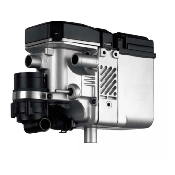
Water Heater Unit
Thermo Top E Additional Heater
Thermo Top C Additional Heater
Thermo Top P Additional Heater
Installation Instructions
Citroen C4 Picasso
Gasoline and Diesel
from Model Year 2006
Left-hand drive vehicle
WARNING!
Hazard warning:
Incorrect installation or repair of Webasto heating systems may cause a fire or result in the
emission of carbon monoxide, which can be fatal. Serious or fatal injuries can be caused as
a result.
Specialist company training, technical documentation, specialized tools and equipment are
required to install and repair Webasto heating and cooling systems.
NEVER attempt to install or repair Webasto heating or cooling systems if you have not
successfully completed the company training and thereby acquired the required technical
skills, or if you do not have access to the required technical documentation, tools and
equipment needed to carry out correct installation and repairs.
ALWAYS follow all Webasto installation and repair instructions and observe all warnings.
Webasto does not accept any liability for defects and damage that are attributable to
installation by untrained staff.
Ident. No.:1311842C_EN
e1
00 0003
e1
00 0002
e1
00 0104
Fee Euro 10.00
Feel the drive
© Webasto AG
Advertisement
Table of Contents

Related Manuals for Webasto Thermo Top E


Summary of Contents for Webasto Thermo Top E
-
Page 1: Installation Instructions
Left-hand drive vehicle WARNING! Hazard warning: Incorrect installation or repair of Webasto heating systems may cause a fire or result in the emission of carbon monoxide, which can be fatal. Serious or fatal injuries can be caused as a result. -
Page 2: Table Of Contents
Citroen C4 Picasso Table of Contents Validity Remote option (Telestart) Heater Unit/Installation Kit Preparing heater unit Foreword Preparing installation location General Instructions Installing heater unit Special Tools Water Explanatory Notes on Document Fuel Preliminary Work Gasoline Heater unit installation location Diesel Preparing electrical system Combustion air... -
Page 3: Heater Unit/Installation Kit
1311846B Heater unit recommended for the respective vehicle class: Vehicle Heater unit Compact car Thermo Top E Mid-size car, station wagon Thermo Top C Full-size car, van, offroader Thermo Top P The selection of the heater unit is based on the passenger compartment size of the vehicle and the... -
Page 4: Explanatory Notes On Document
Specific risk of damage to components. Specific risk of fire or explosion. Reference to general installation instructions of Webasto components or to the manufacturer's vehicle- specific documents. Reference to a special technical feature. The arrow in the vehicle icon indicates the position on the vehicle and the angle. -
Page 5: Preliminary Work
Citroen C4 Picasso Preliminary Work WARNING! - Disconnect the battery "earth" or "ground" connection. - Depressurize the cooling system. - Copy the factory number from the original type label to the duplicate type label. - Remove years that do not apply from the duplicate label. - Attach the duplicate label (type label) in the appropriate place. -
Page 6: Preparing Electrical System
Citroen C4 Picasso Preparing electrical system gn/ws 3000 Wires 6 to 9 only with automatic air- 0,5² conditioning br 500 br 500 0,75² 0,75² Cutting wires to rt 2000 length 0,75² rt 500 rt 500 rt 500 0,75² 0,75² 0,75² sw 500 sw 500 0,75²... -
Page 7: Electrical System
Citroen C4 Picasso Electrical system Connecting positive wire Wiring harness pass through Before installing, crimp 8 mm dia. cable lug onto Route wiring harnesses (digital timer, fan positive wire. controller and green/white (gn/ws wire in protective sleeving) on original vehicle wiring 1 Red (rt) wire harness 1 to protective rubber plug 2 and route 2 Original vehicle positive support point... -
Page 8: Fan Controller For Manual Air Conditioning
8045 2V NR gr/br 0,5² IPCU 0,75² gr/br 0,75² 0,5² 26V JN 8021 Webasto components Vehicle components Colors and symbols Heater unit TT-C/E 8021 Air-conditioning control unit rt 6-pin heater unit connector 8071 Air distribution white 25 A fuse 8048... -
Page 9: Automatic Air-Conditioning Fan Controller
0,5² 0,75² 0,75² 26V JN 8080 K3.1 rt/gr 0,5² 4V NR 0,75² 8071 Webasto components Vehicle components Colors and symbols Heater unit TT-C/E 8080 Air-conditioning control unit rt 6-pin heater unit connector 8071 Air distribution white 25 A fuse 8048... - Page 10 Citroen C4 Picasso Fan controller on all vehicles Fan motor is controlled on 2-pin connector 2 of fan module. Produce connections as shown in wiring diagram. Connec- tion to fan 1 Orange (or) wire connector 2V NR, Pin 2 module 3 Orange (or) wire of fan relay 8048 4 Y-adapter 5 Black (sw) wire from K3/30...
- Page 11 Citroen C4 Picasso Also with automatic air-conditioning Brown (br) wire 2 with 6 mm dia. cable lug on original vehicle bolt. Connect red (rt) wire 4 from IPCU/15 to K3.1/86 according to wiring diagram. Installing K3.1 relay 1 Self-tapping screw on existing hole 3 K3.1 relay Control changeover of air distribution is carried out on 4-pin connector 4V NR 2 from...
-
Page 12: Digital Timer, Summer/Winter Switch Option
Citroen C4 Picasso Digital timer, summer/winter switch option Installation location shown is a recommendation. Agree upon with final customer before installing. Installing digital 1 Digital timer timer 2 12 mm dia. hole, summer/winter switch Remote option (Telestart) 1 Double-sided adhesive tape 2 Receiver Installing receiver... -
Page 13: Preparing Heater Unit
Citroen C4 Picasso Preparing heater unit 1.8 liter gasoline engine a = 1240 mm 1.6 liter diesel engine Cutting a = 1100 mm coolant hoses to 2.0 liter diesel engine length a = 1200 mm Discard section X 1.8 liter gasoline engine d = 1240 mm 1.6 liter diesel engine d = 1180 mm... -
Page 14: Preparing Installation Location
Citroen C4 Picasso Insert two washers at position 3 between bracket 2 and heater unit 1 . 1 Ejot screw [2x] 3 Ejot screw, washer [2x] Preassem- bling bracket 1 Hose clamp [4x] 2 20x20 connecting pipe [2x] Premount- ing coolant hoses 1 Exhaust pipe 2 Hose clamp [2x]... - Page 15 Citroen C4 Picasso Copy hole pattern as shown. 1 Drill 9.1 mm dia. hole; install rivet nut 610 mm Mounting rivet nut Square cut-out at position 2 . 1 7 mm dia. hole [2x] (centered from bar) 67 mm 318 mm Holes for bracket in radiator...
-
Page 16: Installing Heater Unit
Citroen C4 Picasso 2.0 liter gasoline engine only Cut away edge 1 at marking and discard. Cutting away edge on radiator cross member Cut 5 consecutive 500 mm ends from edge protection provided and install. 1 Edge protection 50 2 Edge protection 70 3 Edge protection 130 Installing 4 Edge protection 60... - Page 17 Citroen C4 Picasso Before installing wind deflector plate 3 , mount wiring harness for heater unit 4 . 1 Loosely mount M6x20 bolt, spring lockwasher and large diameter washer 2 Strut Installing 5 Loosely mount Ejot screw [2x] strut Tighten all connections following installation. 1 M6x20 bolt, spring lockwasher, large diameter washer Installing...
-
Page 18: Water
Citroen C4 Picasso Water WARNING! Any coolant running off should be collected using an appropriate container. Install hoses so that they are kink-free. Unless specified otherwise, always fasten using cable ties. Position clamps so that no other hose can be damaged! When installing the coolant hose, the heater unit must be filled with coolant. - Page 19 Citroen C4 Picasso Turn perforated bracket 2 by approx. 75° in longitudinal axis. 1 M6x20 bolt, flanged nut 2 Perforated bracket 3 Rubber-coated pipe clamp Preparing perforated bracket Slide on heat protection hoses. Route coolant hoses A and D through original vehicle pass through on radiator at left to heater unit.
- Page 20 Citroen C4 Picasso Fasten perforated bracket on transmission block. 1 Prepared perforated bracket 2 Original vehicle bolt Installing perforated bracket 1.8 liter gasoline Route hose A and D through rubber-coated p-clamps. 1 Rubber-coated p-clamp [2x] Routing to cutting point Disconnect hose from engine outlet to heat exchanger inlet with hose clamping pliers.
- Page 21 Citroen C4 Picasso Fasten rubber isolator on hose A with cable tie. 1 Black (sw) rubber isolator Routing in engine compart- ment Align hoses and tighten hose clamps at connecting point of hose A and B on heater unit. Check the position of the components; adjust if necessary.
- Page 22 Citroen C4 Picasso Before installation, push black (sw) rubber isolator 1 onto hose A . 2 Engine outlet hose section 3 Hose section of heat exchanger inlet Connect- ing heat exchanger inlet and engine out- Fasten black (sw) rubber isolator 1 on hole of transmission block with cable tie.
- Page 23 Citroen C4 Picasso Before installing, push black (sw) rubber isolator 1 onto hose A and onto hose section of heat exchanger inlet 3 . 2 Engine outlet hose section Connect- ing heat exchanger inlet and engine out- Fasten black (sw) rubber isolator 1 on original vehicle wiring harness bracket with cable tie.
-
Page 24: Fuel
Citroen C4 Picasso Fuel CAUTION! Open the vehicle's fuel tank cap, ventilate the tank and then re-close the tank lock. Catch any fuel running off with an appropriate container. Install fuel line and metering-pump wiring harness so that they are protected against stone impact. Unless specified otherwise, always fasten using cable ties. - Page 25 Citroen C4 Picasso Remove fuel tank and fuel-tank sending unit 1 according to manufacturer's information. 2 Large diameter washer 3 Copy hole pattern, 6 mm dia. hole Removing fuel Shape fuel standpipe 1 according to template, cut to length and install. Installing fuel standpipe...
-
Page 26: Diesel
Citroen C4 Picasso Connect fuel line from heater unit 1 to pressure side and fuel line from fuel standpipe 3 to intake side of metering pump. 2 Wiring harness of metering pump, connector mounted Connect- 4 Hose section, 10 mm dia. clamps [2x] ing meter- 5 Hose section, 10 mm dia. - Page 27 Citroen C4 Picasso Connect fuel line from heater unit 1 on pressure side and fuel line to fuel standpipe 3 on intake side of metering pump. 2 Wiring harness of metering pump, connector mounted Connect- 4 Hose section, 10 mm dia. clamps [2x] ing meter- 5 Hose section, 10 mm dia.
-
Page 28: Combustion Air
Citroen C4 Picasso Combustion air 1 Combustion air pipe a = 250 Discard section X Cutting combus- tion air pipe to length Drill 6.2 mm dia. hole 1 in center of grid as shown. 300 mm Hole for muffler Ensure proper installation position of air intake muffler, see "Installation Instructions“. -
Page 29: Exhaust Gas
Citroen C4 Picasso Exhaust gas Following installation, bend muffler upward approx. 30°. 1 Muffler Installing 2 Hose clamp exhaust 3 Exhaust pipe system 4 M6x20 bolt, spring lockwasher 5 Perforated bracket 6 M6x20 bolt, flanged nut Lay on red (rt) rubber isolator at position 1 , copy hole pattern and drill 42 mm dia. -
Page 30: Final Work
- Check the proper operation of the additional heater, see the operating instructions/installation instructions. - Attach the "Switch off additional heater before refueling" sticker to the left-hand B-pillar. Feel the drive Webasto AG Postfach 80 - 82132 Stockdorf Hotline 01805 / 932278 - Hotfax 0395 / 5592-353 http://www.webasto.de... -
Page 31: Operating Instructions For End Customer
Citroen C4 Picasso Operating Instructions for End Customer Please remove page and add to the vehicle operating instructions. Note: We recommend matching the heating time to the driving time. Heating time = driving time Example: For a driving time of approx. 20 min. (in one direction), we recommend not exceeding a switch-on time of 20 min. -
Page 32: Template For Gasoline Fuel Standpipe
Citroen C4 Picasso Template for Gasoline Fuel Standpipe 100 mm Scale 1:1 Compare the size of the printed version with dimension lines. Permitted tolerance a maximum of 2%. Set the printer settings to “no margin” or “minimize margins” and 100% of the normal size. 100 mm 1311842C_EN...
Need help?
Do you have a question about the Thermo Top E and is the answer not in the manual?
Questions and answers