Webasto thermo top e Installation Instructions Manual
Parking heater toyota verso
Hide thumbs
Also See for thermo top e:
- Installation documentation (41 pages) ,
- Installation instructions manual (36 pages) ,
- Manual (31 pages)
Table of Contents
Advertisement
Quick Links
Water Heater
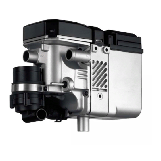
Thermo Top E Parking Heater
Thermo Top C Parking Heater
Thermo Top P Parking Heater
Installation instructions
Toyota Verso
Diesel
from Model Year 2009
For left-hand drive vehicles only
Automatic air-conditioning
Manual / automatic transmission
WARNING!
Hazard warning:
Incorrect installation or repair of Webasto heating systems may cause a fire or result in the
emission of carbon monoxide, which can be fatal. Serious or fatal injuries can be caused as
a result.
Specialist company training, technical documentation, specialised tools and equipment are
required to install and repair Webasto heating and cooling systems.
Only original Webasto parts must be used. For this, also see the catalog of air and water heat-
er accessories from Webasto.
NEVER attempt to install or repair Webasto heating or cooling systems if you have not
successfully completed the company training and thereby acquired the required tech-
nical skills, or if you do not have access to the required technical documentation, tools
and equipment needed to carry out correct installation and repairs.
ALWAYS follow all Webasto installation and repair instructions and observe all warnings.
Webasto does not accept any liability for defects and damage that are attributable to installa-
tion by untrained staff.
Ident. No.: 1315129B_EN
e1
00 0003
e1
00 0002
e1
00 0104
Fee Euro 10.00
Feel the drive
© Webasto AG
Advertisement
Table of Contents

Subscribe to Our Youtube Channel
Related Manuals for Webasto thermo top e


Summary of Contents for Webasto thermo top e
-
Page 1: Installation Instructions
Specialist company training, technical documentation, specialised tools and equipment are required to install and repair Webasto heating and cooling systems. Only original Webasto parts must be used. For this, also see the catalog of air and water heat- er accessories from Webasto. -
Page 2: Table Of Contents
Toyota Verso Table of Contents Validity Remote option (Telestart) Heater/Installation Kit Preparing installation location Foreword Installing heater General Instructions Water Special Tools Fuel Explanatory Notes on Document Exhaust system Preliminary Work Combustion air Heater installation location Final Work Preparing electrical system Operating Instructions for End Customer Electrical Connections Fan controller... -
Page 3: Heater/Installation Kit
1315128A Heater recommended for the respective vehicle class: Vehicle Heater Compact car Thermo Top E Mid-size car, station wagon Thermo Top C Full-size car, van, offroader Thermo Top P The selection of the heater is based on the passenger compartment size of the vehicle and the level of... -
Page 4: Explanatory Notes On Document
Toyota Verso Explanatory Notes on Document To provide you with a quick overview of the individual working steps, you will find an identification mark on the outside top right corner of the page in question. Mechanical system Electrical system Coolant connection Fuel connection Exhaust system Combustion air... -
Page 5: Preliminary Work
Toyota Verso Preliminary Work WARNING! - Open the fuel tank cap, ventilate the tank. - Close the tank cap again. - Disconnect the battery "earth" or "ground" connection. - Depressurize the cooling system. - Copy the factory number from the original type label to the duplicate type label. - Remove years that do not apply from the duplicate label. -
Page 6: Preparing Electrical System
Toyota Verso Preparing electrical system All vehicles Cut corrugated tube provided to length. Cutting 1 10 mm dia. corrugated tube, 2,100 mm corrugat- long ed tube to 2 17 mm dia. corrugated tube, 700 mm long length Replace 25 A fuse F3 with 10 A fuse. 1 M5x20 bolt, washer, flanged nut 2 Retaining plate for fuse holder 3 Fuses pushed on... -
Page 7: Electrical Connections
Toyota Verso Electrical Connections Wiring harness pass through Wiring harness pass through 1 Protective rubber plug 1 Wiring harnesses of digital timer and fan con- troller 2 Corrugated tube Do not install the metering pump cable har- ness until later together with fuel pipe along the original vehicle fuel lines in the corru- gated tube on the underbody Wiring har-... - Page 8 Toyota Verso Positive wire Digital timer and summer/winter switch op- tion 1 Positive battery terminal 2 Cut positive wire to length, 8 mm dia. cable lug 1 Digital timer 2 Summer/winter switch, drilled hole 12 mm dia. Wiring har- ness in- stallation diagram Ground wire...
-
Page 9: Fan Controller
Toyota 30/B 15/IG Wiring dia- gram 0,5² rt/ws 0,5² 4² 4² ws/sw 31/Gnd Webasto components Vehicle components Colours and symbols Heater TT-C/E Fan unit 6-pin connector GE connector white Replace 25 A with 10 A AC control black fuse. 40-pin ACC connector... -
Page 10: Toyota Verso
Toyota Verso Connection to 40-pin connector 1 from ACC Produce connections as shown in wiring dia- gram. 2 Yellow (ge) wire HTR/IG 3 Red (rt) wire of K3/87a Connec- 4 Black (sw) wire of K3/30 tion to ACC 5 Yellow (ge) wire of connector D47/1 Remote option (Telestart) Fasten receiver 1 with adhesive tape. -
Page 11: Preparing Installation Location
Toyota Verso Preparing installation location 1 Bracket 2 Drill out hole to 8.5 mm dia. Drilling bracket When installing bracket, align it parallel to original vehicle edge 2 . Insert 20mm shim between bracket and vehi- cle! 1 M8x40 bolt, 20 mm shim Copying 3 Copy hole pattern, 7 mm dia. -
Page 12: Installing Heater
Toyota Verso 1 Angle bracket 2 M6x35 bolt, large diameter washer, 20 mm shim, flanged nut 3 Exhaust muffler Preassem- bling ex- haust muffler A 20 mm shim must be positioned between bracket and vehicle at position 2 . 1 70 mm edge protection [2x] 2 M8x40 bolt, spring lockwasher, 20mm shim, existing threaded hole Installing... - Page 13 Toyota Verso 1 Loosely mount Ejot screw [2x] Installing heater Position angle bracket 2 between heater and bracket. Tighten all bolts. 1 Ejot screw 3 Preassembled exhaust muffler Installing heater 1315129B_EN...
-
Page 14: Water
Toyota Verso Water WARNING! Tighten all hose clamps to 2.0 + 0.5 Nm. Any coolant running off should be collected using an appropriate container! Install hoses so that they are kink-free. Unless specified otherwise, always fasten using cable ties. Po- sition hose and spring clips so that no other hose can be damaged! The connection should be "inline"... - Page 15 Toyota Verso A 15x18 90° molded hose provided C 20x20 90° molded hose provided D 20x20 180° molded hose provided Discard sections X. b = 900 Cutting d = 40 coolant e = 560 hoses to length Push braided protection hose onto hose B and E and cut to length.
- Page 16 Toyota Verso Connect hose A on engine outlet and connect to 180° elbow from hose B . Connect- ing engine outlet Cut rub protection 1 provided in half. Glue one section onto charge-air tube in area of spring clips 2 . Gluing rub protection Slide black (sw) rubber isolator 1 onto...
- Page 17 Toyota Verso 1 Original vehicle line 2 Hose on heat exchanger inlet 3 Spacer bracket Fastening hose to heat ex- changer in- 1 Hose on heat exchanger inlet Connect- ing heat exchanger inlet 1 M6x20 bolt, pin lock in existing hole [2x each] 2 Rubber-coated pipe clamp [2x] Installing...
-
Page 18: Fuel
Toyota Verso Fuel CAUTION! Open the vehicle's fuel tank cap, ventilate the tank and then re-close the tank lock. Catch any fuel running off with an appropriate container. Install fuel line and metering-pump wiring harness so that they are protected against stone impact. Un- less specified otherwise, always fasten using cable ties. - Page 19 Toyota Verso Remove rubber plugs and mount rivet nut at position 1 . Installing rivet nut 1 Silent block, flanged nut 2 Metering pump 3 Rubber-coated pipe clamp Installing metering pump 1 Wiring harness of metering pump, connec- tor mounted 2 Hose section, 10 mm dia.
-
Page 20: Exhaust System
Toyota Verso Exhaust system 1 Exhaust pipe a = 180 2 Exhaust end section b = 260 Preparing exhaust Discard section X pipe 1 Hose clamp [2x] 2 Exhaust pipe Installing exhaust pipe 1 Hose clamp 2 Exhaust end section 3 Red (rt) rubber isolator with groove 4 Position red (rt) rubber isolator Installing... -
Page 21: Combustion Air
Toyota Verso Combustion air 1 Combustion air pipe a = 290 Discard section X Cutting combus- tion air pipe to length Drill out original vehicle hole 1 to 9.1mm dia. and mount M6 rivet nut! Installing rivet nut 1 Combustion-air intake pipe 2 27 mm dia. -
Page 22: Final Work
Toyota Verso Final Work WARNING! Reassemble the disassembled components in reverse order. Check all hoses, clamps and all electrical connections for firm seating. Secure all loose cables using cable ties. Only use manufacturer-approved coolant. Spray the heater components with anti-corrosion wax (Tectyl 100K, Order No. -
Page 23: Operating Instructions For End Customer
Toyota Verso Operating Instructions for End Customer Please remove page and add to the vehicle operating instructions. Note: We recommend matching the heating time to the driving time. Heating time = driving time Example: For a driving time of approx. 20 min. (in one direction), we recommend not exceeding a switch-on time of 20 min. - Page 24 Toyota Verso 1315129B_EN...
- Page 25 Toyota Verso 1315129B_EN...
- Page 26 Toyota Verso Feel the drive Webasto AG Postfach 80 D-82131 Stockdorf / Germany National Hotline: 01805 93 22 78 (14 Cent aus dem deutschen Festnetz) Hotfax: 0395 5592 353 Hotmail: hotline@webasto.de http://www.webasto.de Printed in Germany 07/2010 Printing: Stef- 1315129B_EN...
Need help?
Do you have a question about the thermo top e and is the answer not in the manual?
Questions and answers