Webasto Thermo Top E Installation Documentation
Vw golf vi, golf plus, golf variant water heater
Hide thumbs
Also See for Thermo Top E:
- Installation documentation (41 pages) ,
- Installation instructions manual (36 pages) ,
- Manual (31 pages)
Table of Contents
Advertisement
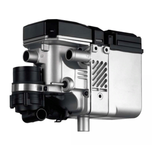
Water Heater
Thermo Top E Parking Heater
Thermo Top C Parking Heater
Thermo Top P Parking Heater
Installation documentation
VW Golf VI, Golf Plus, Golf Variant
1.2 and 1.4 TSI
from Model Year 2008
Left-hand drive vehicle
WARNING!
Hazard warning:
Incorrect installation or repair of Webasto heating systems may cause a fire or result in the
emission of carbon monoxide, which can be fatal. Serious or fatal injuries can be caused as
a result.
Specialist company training, technical documentation, specialised tools and equipment are
required to install and repair Webasto heating and cooling systems.
Only original Webasto parts must be used. For this, also see the catalog of air and water heat-
er accessories from Webasto.
NEVER attempt to install or repair Webasto heating or cooling systems if you have not
successfully completed the company training and thereby acquired the required tech-
nical skills, or if you do not have access to the required technical documentation, tools
and equipment needed to carry out correct installation and repairs.
ALWAYS follow all Webasto installation and repair instructions and observe all warnings.
Webasto does not accept any liability for defects and damage that are attributable to installa-
tion by untrained staff.
Ident. No.: 1314421C_EN
e1
00 0003
e1
00 0002
e1
00 0104
Fee Euro 10.00
Feel the drive
© Webasto AG
Advertisement
Table of Contents

Related Manuals for Webasto Thermo Top E


Summary of Contents for Webasto Thermo Top E
- Page 1 Specialist company training, technical documentation, specialised tools and equipment are required to install and repair Webasto heating and cooling systems. Only original Webasto parts must be used. For this, also see the catalog of air and water heat- er accessories from Webasto.
-
Page 2: Table Of Contents
VW Golf VI, Golf Plus, Golf Variant Table of Contents Validity Preparing exhaust system Heater/Installation Kit Installing heater Foreword Fuel General Instructions Coolant circuit Special Tools 1.2 Manual transmission Explanatory Notes on Document 1.4 90kW manual transmission Preliminary Work 1.4 90kW DSG Heater installation location 1.4 118 kW manual transmission Electrical system... -
Page 3: Heater/Installation Kit
VW Golf VI, Golf Plus, Golf Variant Heater/Installation Kit Quantity Description Order No.: Retail accessories Thermo Top E / C / P See price list Installation kit for VW Golf VI, Golf Plus, Golf Variant 1.2 and 1314420B 1.4 TSI... -
Page 4: Explanatory Notes On Document
VW Golf VI, Golf Plus, Golf Variant Explanatory Notes on Document You will find an identification mark on the outside top right corner of the page in question to provide you with a quick overview of the individual working steps. Mechanical system Electrical system Coolant circuit... -
Page 5: Preliminary Work
VW Golf VI, Golf Plus, Golf Variant Preliminary Work WARNING! - Open the fuel tank cap, ventilate the tank. - Close the fuel tank cap again. - Depressurise the cooling system. - Copy the factory number from the original type label to the duplicate type label. - Remove years that do not apply from the duplicate label. -
Page 6: Electrical System
VW Golf VI, Golf Plus, Golf Variant Electrical system Wiring harness routing Wiring harness pass through Route excess lengths from wiring harness 1 in 1 Original vehicle wiring harness pass through cable duct 2 below battery and secure with cable ties. -
Page 7: Fuse Holder And K3 Relay
VW Golf VI, Golf Plus, Golf Variant Fuse holder and K3 relay Countersink holes 3 from behind for M5 coun- tersunk head screws. 1 Cover of fuse/relay carrier in engine com- Holes in partment cover 2 Cut away bar in shaded area 3 5 mm dia. -
Page 8: Climatic Fan Control
T10k rt/ws rt/ge 4² 4² (sw/ge) 4² 4² J301 rt/sw 4² Webasto components Vehicle components Colours and symbols Heater TT-C/P/E Fan motor 6-pin heater connector F1 Fuse 40A (depending on respec- yellow tive fuse assignment) 25 A fuse black Golf VI = SC22 or SC40... - Page 9 VW Golf VI, Golf Plus, Golf Variant Golf VI and Variant Connection on fuse carrier 2 (instrument pan- el at upper left). Remove red/yellow (rt/ge) 4² wire 1 on fuse output SC 22 or SC40 (de- pending on respective vehicle equipment). Connec- tion to fuse carrier...
-
Page 10: Climatronic Fan Control
T10k 0,75² sw/ws 0,75² rt/ws IPCU 4² 4² 0,35² gn/ws J126 Webasto components Vehicle components Colours and symbols Heater TT-C/P/E Fuse 40A (depending on re- 6-pin heater connector spective fuse assignment) of white SC22 or SC56 Fan relay black Replace 25 A fuse... - Page 11 VW Golf VI, Golf Plus, Golf Variant Golf VI and Variant Produce connections as shown in wiring dia- gram. Position of free sockets depends on respec- tive vehicle equipment. Installing IPCU sock- Note: Attach IPCU socket 1 with cable ties for new shape of the fuse carrier.
- Page 12 VW Golf VI, Golf Plus, Golf Variant Route wiring harness IPCU 2 along cross member 1 to centre console. Routing wiring har- ness from IPCU All vehicles Route wiring harness of IPCU 1 to centre con- sole. Routing wiring har- ness from IPCU Route wiring harness of IPCU 1 to fan unit.
-
Page 13: Digital Timer, Summer/Winter Switch Option
VW Golf VI, Golf Plus, Golf Variant Digital timer, summer/winter switch option Golf VI and Variant 1 Digital timer Digital tim- 2 12 mm dia. hole; summer/winter switch Golf Plus 1 Digital timer 2 12 mm dia. hole; summer/winter switch Digital tim- Remote option (Telestart) Golf VI and Variant... - Page 14 VW Golf VI, Golf Plus, Golf Variant Golf Plus Bend down lower tab of bracket by 90° and drill out hole to 6.5 mm dia. as shown. 1 Receiver Installing 2 Bracket receiver 3 M6 bolt, large diameter washer (between bracket instrument carrier), large diameter washer (from outside), flanged nut 4 Instrument carrier, existing hole...
-
Page 15: Premounting Heater
VW Golf VI, Golf Plus, Golf Variant Premounting heater 1 Ejot stud Premount- ing heater 1 Combustion air pipe a = 250 Discard section X Cutting combus- tion air pipe to length Insert one washer each between heater and bracket at positions 2 . 1 M6x30 spacer nut 2 Ejot screw, washer [2x each] 3 27 mm dia. -
Page 16: Preparing Exhaust System
VW Golf VI, Golf Plus, Golf Variant Preparing exhaust system 1 Exhaust pipe a = 190 2 Exhaust end section b = 240 Cutting ex- haust pipe Discard section X to size Slide insulation 2 onto exhaust pipe. 1 Hose clamp [2x] Premount- ing ex- haust pipe... -
Page 17: Installing Heater
VW Golf VI, Golf Plus, Golf Variant Preparing installation location Prevent large diameter washer from falling by securing with putty etc. 1 Large diameter washer on original vehicle Preparing stud bolt [3x] installa- 2 100 mm edge protection tion loca- tion Installing heater 1 Large diameter washer, flanged nut M8... -
Page 18: Fuel
VW Golf VI, Golf Plus, Golf Variant Fuel CAUTION! Open the vehicle's fuel tank cap, ventilate the tank and then re-close the tank lock. Catch any fuel running off in an appropriate container. Install fuel line and metering pump wiring harness so that they are protected against stone impact. Un- less specified otherwise, always fasten using cable ties. - Page 19 VW Golf VI, Golf Plus, Golf Variant 1 Silent block, large diameter washer, M6 flanged nut 2 Sealing plug removed Installing silent block 1 Wiring harness of metering pump, connec- tor mounted 2 Secure rubber-coated p-clamp on silent block with flanged nut 3 Metering pump 4 Plug remounted Installing...
- Page 20 VW Golf VI, Golf Plus, Golf Variant Cut 3 mm off blind plug 1 . 2 Fuel-tank sending unit Cutting off blind plug Ensure sufficient distance from adjacent com- ponents, especially from fuel gauge. 1 13.5mm dia. Caillau clamp 2 Fuel line 3 10 mm dia.
-
Page 21: Coolant Circuit
VW Golf VI, Golf Plus, Golf Variant Coolant circuit WARNING! Any coolant running off should be collected in an appropriate container. Install hoses so that they are kink-free. Unless specified otherwise, always fasten using cable ties. Position clamps so that other hos- es cannot be damaged. -
Page 22: Manual Transmission
VW Golf VI, Golf Plus, Golf Variant 1.2 Manual transmission Discard section X . Cutting hoses to length Push braided protection hoses onto hose A and C , cut to length and shrink. 1 Heat shrink plastic tubing [4x] Premount- ing hoses Turn clamp lock 1 [2x] toward the engine. - Page 23 VW Golf VI, Golf Plus, Golf Variant Install hose A with 180° elbow on connection piece of engine outlet. 1 Original vehicle spring clip Connect- ing engine outlet Routing in engine compart- ment Combustion air silencer tied back for demon- stration purposes.
-
Page 24: 90Kw Manual Transmission
VW Golf VI, Golf Plus, Golf Variant Insert black (sw) rubber isolator 2 in connect- ing point. 1 Hose on heat exchanger inlet Connect- ing heat exchanger inlet Align black (sw) rubber isolator 2 on bracket of manual gearshift. Align hoses and attach with cable tie 3 on original vehicle hose. - Page 25 VW Golf VI, Golf Plus, Golf Variant Push braided protection hoses onto hose A and C , cut to length and shrink. 1 Heat shrink plastic tubing [4x] Premount- ing hoses Turn clamp lock 1 [4x] toward the engine. Twisting clamps Pull off hose on engine outlet/heat exchanger inlet 2 on connection piece of engine outlet.
- Page 26 VW Golf VI, Golf Plus, Golf Variant Routing in engine compart- ment Combustion air silencer tied back for demon- stration purposes. Connect- ing heater Routing in engine compart- ment 1 Hose on heat exchanger inlet 2 Original vehicle spring clip Connect- ing heat exchanger...
-
Page 27: 90Kw Dsg
VW Golf VI, Golf Plus, Golf Variant Align black (sw) rubber isolator 1 on bracket of manual gearshift. Fasten hose A and C with cable tie 2 to original vehicle hose. Routing in engine compart- ment Align hoses and attach with cable tie 2 on original vehicle hose. - Page 28 VW Golf VI, Golf Plus, Golf Variant Push braided protection hoses onto hose A and C , cut to length and shrink. 1 Heat shrink plastic tubing [4x] Premount- ing hoses 1 50 mm narrow edge protection 2 Straighten earth cable Installing edge pro- tection...
- Page 29 VW Golf VI, Golf Plus, Golf Variant Routing in engine compart- ment Combustion air silencer tied back for demon- stration purposes. Connect- ing heater Routing in engine compart- ment Install hose A with 180° elbow on connection piece of engine outlet. 1 Original vehicle spring clip Connect- ing engine...
- Page 30 VW Golf VI, Golf Plus, Golf Variant 1 M6x20 bolt, flanged nut 2 Angle bracket 3 29 mm dia. rubber-coated p-clamp [2x] Fastening hoses 1 6 mm dia. hole 2 Battery carrier Preparing battery car- rier Install battery carrier 2 . Loosely assemble clip-type cable tie 1 around hose A and C ! Fastening hoses...
-
Page 31: 118 Kw Manual Transmission
VW Golf VI, Golf Plus, Golf Variant Aligning hoses Fasten black (sw) rubber isolator 1 on with cable tie 3 on hose A . Align angle bracket on position 2 to the original vehicle hole. Fastening hoses Install battery. Ensure sufficient distance from neighbouring components. - Page 32 VW Golf VI, Golf Plus, Golf Variant Push braided protection hoses onto hose A and C , cut to length and shrink. 1 Heat shrink plastic tubing [4x] Premount- ing hoses 1 Clip-type cable tie [2x] 2 Bracket for coolant hoses Preparing bracket for coolant...
- Page 33 VW Golf VI, Golf Plus, Golf Variant 1 Hose on heat exchanger inlet Connect- ing heat exchanger inlet Routing in engine compart- ment Combustion air silencer tied back for demon- stration purposes. Connect- ing heater Install hose A with 180° elbow on connection piece of engine outlet.
- Page 34 VW Golf VI, Golf Plus, Golf Variant Drill out perforated bracket 2 to 8.5 mm dia. at position 3 . 1 M6x20 bolt, flanged nut 3 Original vehicle bolt 4 29 mm dia. rubber-coated p-clamp [2x] Fastening hoses Ensure sufficient distance from neighbouring components.
-
Page 35: All Vehicles
VW Golf VI, Golf Plus, Golf Variant All vehicles Position of drain pipe may vary. Glue rub protection 2 [2x] onto air filter box 1 as shown. Preparing air filter Version 1: If drain pipe 1 present as shown, then route parallel to coolant hose C . -
Page 36: Exhaust Gas
VW Golf VI, Golf Plus, Golf Variant Exhaust gas Ensure sufficient space between exhaust end section and transmission and wheel well trim. (Figure shows vehicle with DSG) Aligning 1 Wheel well trim exhaust end sec- tion Remove insulation at position 2 if present. 1 Underride protection 2 42 mm dia. -
Page 37: Final Work
- Select channel 15 - Input the new value "100" (the value 100 corresponds to 50%) - Save these settings Feel the drive Webasto AG Postfach 80 D-82132 Stockdorf / Germany National Hotline: 01805 93 22 78 (14 Cent aus dem deutschen Festnetz) Hotfax: 0395 5592 353 Hotmail: technikcenter@webasto.com... -
Page 38: Operating Instructions For End Customer
VW Golf VI, Golf Plus, Golf Variant Operating Instructions for End Customer Please remove page and add to the vehicle operating instructions. Note: We recommend matching the heating time to the driving time. Heating time = driving time Example: For a driving time of approx. 20 min. (in one direction), we recommend not exceeding a switch-on time of 20 min.
Need help?
Do you have a question about the Thermo Top E and is the answer not in the manual?
Questions and answers