Table of Contents
Advertisement
Quick Links
www.ti.com
EVM User's Guide: AMC8V208EVM
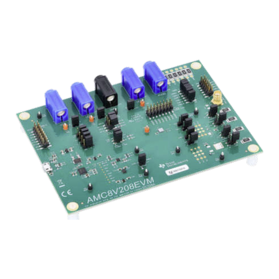
AMC8V208 Evaluation Module
Description
The AMC8V208EVM is an easy-to-use platform to
evaluate the functionality and performance of the
AMC8V208. The AMC8V208EVM has optional circuits
and jumpers to configure the AMC8V208 for different
applications. This EVM features the AMC8V208, a
highly integrated current-output and control device
optimized for optical networking applications.
Get Started
1. Order the
AMC8V208EVM
2. Download and install the AMC8V208EVM
software.
SLAU932 – OCTOBER 2024
Submit Document Feedback
on ti.com.
Copyright © 2024 Texas Instruments Incorporated
3. Configure the hardware jumper settings.
4. Connect the USB and external AMC8V208EVM
supplies.
5. Launch the AMC8V208EVM GUI.
Features
•
Onboard 1.8V VIO supply
•
Jumpers to evaluate different device configurations
•
Onboard FT4222 controller for SPI or I
communication
Applications
•
Optical module
•
Optical line cards
Description
2
C
AMC8V208 Evaluation Module
1
Advertisement
Table of Contents

Related Manuals for Texas Instruments AMC8V208


Summary of Contents for Texas Instruments AMC8V208
- Page 1 5. Launch the AMC8V208EVM GUI. AMC8V208. The AMC8V208EVM has optional circuits Features and jumpers to configure the AMC8V208 for different applications. This EVM features the AMC8V208, a • Onboard 1.8V VIO supply highly integrated current-output and control device •...
-
Page 2: Kit Contents
The contents of the EVM kit is shown in Table 1-1. Contact the nearest TI Product Information Center if any component is missing. Make sure to verify the latest versions of the related software at the Texas Instruments website, www.ti.com. Table 1-1. AMC8V208EVM Kit Contents... -
Page 3: Device Information
The USB connection generates a 5V supply for the EVM. The onboard controller generates 3.3V of power for the input/output (IO) signals generated by the onboard controller. These IO signals are level translated to the IO supply voltage (VIO) of the AMC8V208. An onboard voltage regulator generates 1.8V for use as the AMC8V208 IO supply voltage. - Page 4 4.99Ω load resistor to measure the 3-4 open: IDAC1+ output disconnected from resistor current as a function of the voltage. 4.99Ω load resistor. AMC8V208 Evaluation Module SLAU932 – OCTOBER 2024 Submit Document Feedback Copyright © 2024 Texas Instruments Incorporated...
-
Page 5: Connecting The Hardware
SMA jack for MUX_OUT monitoring IDAC1+ external mode output IDAC2+ external mode output IDAC1+ internal mode output IDAC2+ internal mode output FT4222 digital signals IDAC outputs PVDD inputs SLAU932 – OCTOBER 2024 AMC8V208 Evaluation Module Submit Document Feedback Copyright © 2024 Texas Instruments Incorporated... -
Page 6: Software Installation
AMC8V208 registers and functions. 3.2.1 Starting the Software To launch the software, navigate to the Texas Instruments folder in the Start menu, and select the AMC8V208EVM icon. If the onboard controller is connected correctly, then the status bar at the bottom of the screen displays... -
Page 7: Software Features
The menu bar displays the High Level Configuration page with the AMC Control subpage, and the Low Level Configuration page. Before using the GUI, see the respective device data sheet for detailed AMC8V208 programming instructions. SLAU932 – OCTOBER 2024... - Page 8 3.2.2.1 High Level Configuration Page The High Level Configuration page that provides an interface to quickly configure the parameters and relevant register settings for the respective AMC8V208 device is shown in Figure 3-3. The High Level Configuration page is comprised of the AMC Control subpage. The AMC Control subpage is used to set the range and outputs for the IDACs.
- Page 9 Write Selected or Write Modified buttons are pressed. By default, Immediate Update Mode is selected for the Low Level Configuration page write operations. The AMC8V208 SDO pin must be enabled in the SDO_EN register before reading any device registers. Figure 3-5. Low Level Configuration Page Options SLAU932 –...
- Page 10 SON, 2mm x 2mm WLP, 1mm x 1.5mm CSD25404Q3 SH-J18 SH-J19 4.99 4.99 SH-J11 RSNSP1_IDACP1 4.99 SH-J12 RSNSP2_IDACP2 4.99 SH-J13 SH-J14 Figure 4-1. AMC8V208EVM Schematic Page 1 AMC8V208 Evaluation Module SLAU932 – OCTOBER 2024 Submit Document Feedback Copyright © 2024 Texas Instruments Incorporated...
- Page 11 I2C ADDR SELECT AMC_SDI SH-J3 10.0k SH-J15 AMC_SDA AMC_SCLK_SDA SH-J17 AMC_SCLK SH-J4 AMC_SCL AMC_CS_SCL AMC_CS SH-J5 DIGITAL SIGNALS Figure 4-3. AMC8V208EVM Schematic Page 3 SLAU932 – OCTOBER 2024 AMC8V208 Evaluation Module Submit Document Feedback Copyright © 2024 Texas Instruments Incorporated...
- Page 12 VCCIO_FTDI AMC_VIO VCCIO_FTDI AMC_VIO 100nF 100nF VCCA VCCB 100nF 100nF FTDI_SDO AMC_SDO VCCA VCCB FTDI_GPIO_2 AMC_RESET SN74AXC1T45QDCKRQ1 SN74AXC1T45QDCKRQ1 Figure 4-5. AMC8V208EVM Schematic Page 5 AMC8V208 Evaluation Module SLAU932 – OCTOBER 2024 Submit Document Feedback Copyright © 2024 Texas Instruments Incorporated...
-
Page 13: Pcb Layout
Figure 4-6. AMC8V208EVM PCB Top Layer Layout Figure 4-7. AMC8V208EVM PCB Mid Layer 1 Layout (Ground Plane) Figure 4-8. AMC8V208EVM PCB Mid Layer 2 Layout (Signal Layer) SLAU932 – OCTOBER 2024 AMC8V208 Evaluation Module Submit Document Feedback Copyright © 2024 Texas Instruments Incorporated... - Page 14 Figure 4-9. AMC8V208EVM PCB Mid Layer 3 Layout (Power Layer) Figure 4-10. AMC8V208EVM PCB Mid Layer 4 Layout (Ground Plane) Figure 4-11. AMC8V208EVM PCB Bottom Layer Layout AMC8V208 Evaluation Module SLAU932 – OCTOBER 2024 Submit Document Feedback Copyright © 2024 Texas Instruments Incorporated...
- Page 15 J30, J31, J32 Header, 2.54mm, 2x1, TH Header, 100mil, 2x1, TH HTSW-102-07-G-S Samtec 600Ω Ferrite Bead, 600 ohm at 100MHz, 1A, 0603 782633601 Wurth Elektronik SLAU932 – OCTOBER 2024 AMC8V208 Evaluation Module Submit Document Feedback Copyright © 2024 Texas Instruments Incorporated...
- Page 16 VQFN-32 FT4222HQ-D-R FTDI Crystal, 12MHz, 18pF, SMD ABM3 ABM3-12.000MHZ-D2Y-T Abracon Corporation -60 V MOSFET, P-CH, -60 V, -50 A, DPAK DPAK SUD50P06-15L-E3 Vishay- Semiconductor AMC8V208 Evaluation Module SLAU932 – OCTOBER 2024 Submit Document Feedback Copyright © 2024 Texas Instruments Incorporated...
- Page 17 MOSFET, P-CH, -20 V, -20 A, DQK0006C (WSON-6) DQK0006C CSD25310Q2 Texas Instruments -20 V MOSFET, P-CH, -20 V, -60 A, DQG0008A (VSON- DQG0008A CSD25404Q3 Texas Instruments CLIP-8) SLAU932 – OCTOBER 2024 AMC8V208 Evaluation Module Submit Document Feedback Copyright © 2024 Texas Instruments Incorporated...
-
Page 18: Additional Information
Newer revisions can be available from the TI web site at www.ti.com, or call the Texas Instruments Literature Response Center at (800) 477-8924 or the Product Information Center at (972) 644-5580. When ordering, identify the document by both title and literature number. - Page 19 TI products. TI’s provision of these resources does not expand or otherwise alter TI’s applicable warranties or warranty disclaimers for TI products. TI objects to and rejects any additional or different terms you may have proposed. IMPORTANT NOTICE Mailing Address: Texas Instruments, Post Office Box 655303, Dallas, Texas 75265 Copyright © 2024, Texas Instruments Incorporated...
Need help?
Do you have a question about the AMC8V208 and is the answer not in the manual?
Questions and answers