Table of Contents
Advertisement
Quick Links
This user's guide describes the characteristics, operation, and use of the AMC7834 evaluation boards
(EVMs). This user's guide also discusses the proper setup and configuration of software and hardware,
and reviews various aspects of program operation. A complete circuit description, schematic diagram, and
bill of materials (BOM) are also included.
......................................................................................................................
1
1.1
1.2
2
2.1
2.2
2.3
3
3.1
3.2
4
4.1
4.2
4.3
4.4
4.5
4.6
4.7
4.8
4.9
4.10
4.11
5
5.1
5.2
6
6.1
6.2
6.3
1
AMC7834EVM Hardware Setup
2
3
4
5
6
7
8
Microsoft, Windows, Excel are registered trademarks of Microsoft Corporation.
SLAU608B - December 2014 - Revised May 2016
AMC7834 Evaluation Module
Contents
.......................................................................................
...................................................................................
...........................................................................................
............................................................................................
.............................................................................
.......................................................................................
..................................................................................
..........................................................................................
............................................................................
.........................................................................................
...............................................................................
...................................................................................................
......................................................................................................
..................................................................................
............................................................................
.....................................................................................
......................................................................................
...........................................................................
..............................................................................
...........................................................................................
................................................................................
......................................................................
.........................................................................
List of Figures
...........................................................................................
.....................................................................................
..................................................................................
..........................................................................................
.................................................................................................
.............................................................................................
Copyright © 2014-2016, Texas Instruments Incorporated
SLAU608B - December 2014 - Revised May 2016
...................................................................
.....................................................
..............................................................
...............................................................
.............................................................
.................................................................
...........................................................
AMC7834 Evaluation Module
User's Guide
3
3
3
4
4
5
6
7
7
7
8
8
9
9
9
10
10
11
11
11
12
12
13
13
13
23
23
25
26
4
4
6
7
7
9
9
13
1
Advertisement
Table of Contents

Related Manuals for Texas Instruments AMC7834


Summary of Contents for Texas Instruments AMC7834
-
Page 1: Table Of Contents
SLAU608B – December 2014 – Revised May 2016 AMC7834 Evaluation Module This user's guide describes the characteristics, operation, and use of the AMC7834 evaluation boards (EVMs). This user’s guide also discusses the proper setup and configuration of software and hardware, and reviews various aspects of program operation. - Page 2 External Remote Temperature Inputs .................. AMC7834EVM GPIO Signal Definition ....................... SPI Signal Definition ..................ADC Block Reference Selection ................... AMC7834EVM Bill of Materials AMC7834 Evaluation Module SLAU608B – December 2014 – Revised May 2016 Submit Documentation Feedback Copyright © 2014–2016, Texas Instruments Incorporated...
-
Page 3: Overview
Overview This EVM features the AMC7834 device, a highly integrated, low-power, analog monitoring and control solution for power amplifier biasing capable of current, temperature, and voltage supervision. The AMC7834 integrates a multi-channel (12-bit) ADC, 8 (12-bit) DACs, and four high-side current sense amplifiers supporting common mode voltages from +4-V up to +60-V into a single device. -
Page 4: Amc7834Evm Hardware Setup
4 High-Side Current 2 Remote Temp Input (0í 2.5-V Range) Sense Channels Diode Drivers Figure 2. AMC7834 Test Board Block Diagram AMC7834 Evaluation Module SLAU608B – December 2014 – Revised May 2016 Submit Documentation Feedback Copyright © 2014–2016, Texas Instruments Incorporated... -
Page 5: Signal Definitions Of J4 (20-Pin Male Connector Socket)
GPIO – control output or measure input MISO SPI data input (MISO) DIG_GPIO11 GPIO – control output or measure input SLAU608B – December 2014 – Revised May 2016 AMC7834 Evaluation Module Submit Documentation Feedback Copyright © 2014–2016, Texas Instruments Incorporated... -
Page 6: Theory Of Operation For Sdm-Usb-Dig Platform
PC and translates it into I C, SPI, or other digital I/O patterns. The connected device (in this case, the AMC7834 device) connects to the I/O interface of the platform. During digital I/O transactions, the platform obtains information from the AMC7834 device and sends to the host PC for interpretation. -
Page 7: Amc7834Evm Software Setup
(Note: On Windows XP machines, choose to have the system automatically find the driver or software.) Figure 4. AMC7834EVM Installer Directory Figure 5. AMC7834EVM Install Path SLAU608B – December 2014 – Revised May 2016 AMC7834 Evaluation Module Submit Documentation Feedback Copyright © 2014–2016, Texas Instruments Incorporated... -
Page 8: Amc7834Evm Hardware Overview
(ESD). Customers are advised to observe proper ESD handling precautions when unpacking and handling the EVM, including the use of a grounded wrist strap at an approved ESD workstation. AMC7834 Evaluation Module SLAU608B – December 2014 – Revised May 2016 Submit Documentation Feedback Copyright © 2014–2016, Texas Instruments Incorporated... -
Page 9: Connecting The Hardware
The reference can also be connected to the onboard +2.5-V supply or the external REFIN or REF_ADC/CMP pins located on J3-17 and J3-18, respectively SLAU608B – December 2014 – Revised May 2016 AMC7834 Evaluation Module Submit Documentation Feedback Copyright © 2014–2016, Texas Instruments Incorporated... -
Page 10: Adc/Sense Signal Pins
• 2-3: Connects IOVDD pins to external connector (J11) ADC/SENSE Signal Pins The AMC7834 device contains a multi-channel 12-bit SAR ADC with four external ADC inputs, which range from 0 to +2.5 V. The device also features four high-side current sense amplifiers that have common-mode voltages of 4- to +60-V, and can be programmed for closed-loop (drain current) operation. -
Page 11: Dac Signal Pins
Connect to 2.5-V onboard reference DAC Signal Pins The eight 12-bit DACs of the AMC7834 device are accessible through the J5 connector, as shown in Table 9. The DACs are separated into four bipolar DACs, and four unipolar DACs. The bipolar can be programmed for any of the following ranges: –4- to +1-V, –5- to 0-V, and 0- to 5-V range. -
Page 12: 4.10 Digital Inputs And Gpio Signal Pins
The four GPIO signals on the EVM can be measured on the J6 header. The J6 header also includes most of the digital inputs to the AMC7834 device — these inputs include Sleep1, Sleep2, ALARMOUT, RESET, DACTRIG, and DIGTEST. A signal description of the J6 header is provided in Table Table 12. -
Page 13: Amc7834Evm Software Overview
5.2.1 Software Reset The AMC7834 Software Reset button, shown in Figure 10, resets the AMC7834 device and resets all registers to their default setting. Figure 10. Software Reset Button SLAU608B – December 2014 – Revised May 2016 AMC7834 Evaluation Module Submit Documentation Feedback Copyright ©... - Page 14 The AMC7834EVM features a register map page that allows access to low-level communication by directly writing to and reading from the AMC7834 device’s registers. Selecting a register on the Register Map list presents a description of the values in that register and also displays information such as the register’s address, default value, size, and current value.
- Page 15 14. Selecting a channel enables the button’s respective indicator field for register readout. To view the contents of the read in volts, select Display ADC Value in Volts. SLAU608B – December 2014 – Revised May 2016 AMC7834 Evaluation Module Submit Documentation Feedback Copyright © 2014–2016, Texas Instruments Incorporated...
- Page 16 (Auto) Read. The contents of the chart can be copied into Microsoft Excel ® ® right clicking on the chart and selecting Export Data to Excel. AMC7834 Evaluation Module SLAU608B – December 2014 – Revised May 2016 Submit Documentation Feedback Copyright © 2014–2016, Texas Instruments Incorporated...
- Page 17 AMC7834EVM Software Overview www.ti.com Figure 17. ADC Chart SLAU608B – December 2014 – Revised May 2016 AMC7834 Evaluation Module Submit Documentation Feedback Copyright © 2014–2016, Texas Instruments Incorporated...
- Page 18 DAC input fields are respectively highlighted in green and red boxes. Either one of the DAC input fields can be programmed with the desired DAC output voltage or hexadecimal value. Figure 19. Program DAC Registers AMC7834 Evaluation Module SLAU608B – December 2014 – Revised May 2016 Submit Documentation Feedback Copyright © 2014–2016, Texas Instruments Incorporated...
- Page 19 When cleared to ‘0’, the PA_ON terminal is in the ‘off’ state, when set to ‘1’, the PA_ON terminal is set to the ‘on’ state. Figure 22 displays the PA ON button. Figure 22. PA ON Button SLAU608B – December 2014 – Revised May 2016 AMC7834 Evaluation Module Submit Documentation Feedback Copyright © 2014–2016, Texas Instruments Incorporated...
- Page 20 The temperature sensing inputs also have their respective False alarm protection. The lists for these inputs default to 4 consecutive samples before the alarms are triggered. AMC7834 Evaluation Module SLAU608B – December 2014 – Revised May 2016 Submit Documentation Feedback Copyright © 2014–2016, Texas Instruments Incorporated...
- Page 21 Figure 27. Alarmout 5.2.6 AMC7834EVM GPIO Page The AMC7834 GPIO Page features the four (GPIO1–GPIO4) GPIOs of the AMC7834 device. SLAU608B – December 2014 – Revised May 2016 AMC7834 Evaluation Module Submit Documentation Feedback Copyright © 2014–2016, Texas Instruments Incorporated...
- Page 22 Boolean value of the GPIO register. Press the W/R button to write to or read from the GPIO pin. Figure 29. GPIO Write/Read AMC7834 Evaluation Module SLAU608B – December 2014 – Revised May 2016 Submit Documentation Feedback Copyright © 2014–2016, Texas Instruments Incorporated...
-
Page 23: Amc7834Evm Documentation
DIGTEST REF_IN ALARMOUT VDUT SLEEP2 SLEEP1 DACTRIG RESET SCLK 2.5V REF REF_OUT JP10 Figure 30. AMC7834EVM Schematic (1 of 2) SLAU608B – December 2014 – Revised May 2016 AMC7834 Evaluation Module Submit Documentation Feedback Copyright © 2014–2016, Texas Instruments Incorporated... - Page 24 10 F NEG_5V_SUP JP14 VDUT 600 ohm IOVDD 10 F 0.1 F 0.1 F Figure 31. AMC7834EVM Schematic (2 of 2) AMC7834 Evaluation Module SLAU608B – December 2014 – Revised May 2016 Submit Documentation Feedback Copyright © 2014–2016, Texas Instruments Incorporated...
-
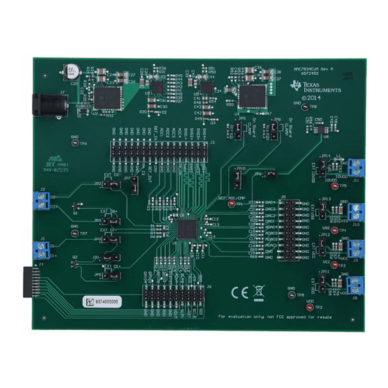
Page 25: Amc7834Evm Pcb Components Layout
AMC7834EVM PCB Components Layout Figure 32 shows the layout of the components for the AMC7834EVM board. Figure 32. AMC7834EVM PCB Components Layout SLAU608B – December 2014 – Revised May 2016 AMC7834 Evaluation Module Submit Documentation Feedback Copyright © 2014–2016, Texas Instruments Incorporated... -
Page 26: Amc7834 Test Board Bill Of Materials
AMC7834EVM Documentation www.ti.com AMC7834 Test Board Bill of Materials Table 15 lists the BOM for this EVM. Table 15. AMC7834EVM Bill of Materials Item Quantity Designator Description Manufacturer Part Number Printed Circuit Board 6572459 C1, C2, C3, C4, C14, C15,... - Page 27 Added note and removed last row in the Contents of AMC7834EVM Kit table................. • Modified the AMC7834EVM Hardware Setup image................• Modified the AMC7834 Test Board Block Diagram image................... • Added a note to the Default Jumper Settings table............•...
- Page 28 STANDARD TERMS AND CONDITIONS FOR EVALUATION MODULES Delivery: TI delivers TI evaluation boards, kits, or modules, including any accompanying demonstration software, components, or documentation (collectively, an “EVM” or “EVMs”) to the User (“User”) in accordance with the terms and conditions set forth herein. Acceptance of the EVM is expressly subject to the following terms and conditions.
- Page 29 FCC Interference Statement for Class B EVM devices NOTE: This equipment has been tested and found to comply with the limits for a Class B digital device, pursuant to part 15 of the FCC Rules. These limits are designed to provide reasonable protection against harmful interference in a residential installation.
- Page 30 【無線電波を送信する製品の開発キットをお使いになる際の注意事項】 開発キットの中には技術基準適合証明を受けて いないものがあります。 技術適合証明を受けていないもののご使用に際しては、電波法遵守のため、以下のいずれかの 措置を取っていただく必要がありますのでご注意ください。 1. 電波法施行規則第6条第1項第1号に基づく平成18年3月28日総務省告示第173号で定められた電波暗室等の試験設備でご使用 いただく。 2. 実験局の免許を取得後ご使用いただく。 3. 技術基準適合証明を取得後ご使用いただく。 なお、本製品は、上記の「ご使用にあたっての注意」を譲渡先、移転先に通知しない限り、譲渡、移転できないものとします。 上記を遵守頂けない場合は、電波法の罰則が適用される可能性があることをご留意ください。 日本テキサス・イ ンスツルメンツ株式会社 東京都新宿区西新宿6丁目24番1号 西新宿三井ビル 3.3.3 Notice for EVMs for Power Line Communication: Please see http://www.tij.co.jp/lsds/ti_ja/general/eStore/notice_02.page 電力線搬送波通信についての開発キットをお使いになる際の注意事項については、次のところをご覧くださ い。http://www.tij.co.jp/lsds/ti_ja/general/eStore/notice_02.page SPACER EVM Use Restrictions and Warnings: 4.1 EVMS ARE NOT FOR USE IN FUNCTIONAL SAFETY AND/OR SAFETY CRITICAL EVALUATIONS, INCLUDING BUT NOT LIMITED TO EVALUATIONS OF LIFE SUPPORT APPLICATIONS.
- Page 31 Notwithstanding the foregoing, any judgment may be enforced in any United States or foreign court, and TI may seek injunctive relief in any United States or foreign court. Mailing Address: Texas Instruments, Post Office Box 655303, Dallas, Texas 75265 Copyright © 2015, Texas Instruments Incorporated...
- Page 32 IMPORTANT NOTICE Texas Instruments Incorporated and its subsidiaries (TI) reserve the right to make corrections, enhancements, improvements and other changes to its semiconductor products and services per JESD46, latest issue, and to discontinue any product or service per JESD48, latest issue.
Need help?
Do you have a question about the AMC7834 and is the answer not in the manual?
Questions and answers