Table of Contents
Advertisement
Quick Links
www.ti.com
User's Guide
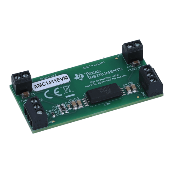
AMC1411 Evaluation Module
The AMC1411 is a precision isolation amplifier with an output separated from the input circuitry by a silicon
dioxide (SiO2) barrier that is highly resistant to magnetic interference. This barrier has been certified to provide
reinforced galvanic isolation of up to 10.5 kV
1
Introduction.............................................................................................................................................................................2
1.1 Features.............................................................................................................................................................................
Interface......................................................................................................................................................................2
2.1 Analog Input.......................................................................................................................................................................
2.2 Shutdown...........................................................................................................................................................................
2.3 Analog Output....................................................................................................................................................................
3 Power Supplies.......................................................................................................................................................................
Input.........................................................................................................................................................................4
Input.........................................................................................................................................................................4
4 EVM Operation........................................................................................................................................................................
4.2 Analog Outputs and VDD2 Power: J4 and J1....................................................................................................................
4.3 Device Operation...............................................................................................................................................................
Layout...........................................................................................................................................................................6
Schematic.............................................................................................................................................7
Materials...................................................................................................................................................................7
6.2 Schematic..........................................................................................................................................................................
Documentation..........................................................................................................................................................9
Figure 2-1. AMC1411EVM Schematic - Analog Input Section....................................................................................................
Figure 2-2. AMC1411EVM Schematic - Analog Output Section.................................................................................................
Figure 3-1. AMC1411EVM Input..................................................................................................................................................
Figure 5-1. AMC1411 Silk Screen Drawing.................................................................................................................................
Figure 6-1. AMC1411EVM Schematic.........................................................................................................................................
Table 4-1. J3 - Analog Input........................................................................................................................................................
Table 4-2. J2 - VDD1 Power........................................................................................................................................................
Table 4-3. J4 - Differential Analog Output...................................................................................................................................
Table 4-4. J1 - VDD2 Power.......................................................................................................................................................
Materials............................................................................................................................................................7
Trademarks
All trademarks are the property of their respective owners.
SBAU373 - APRIL 2021
Submit Document Feedback
ABSTRACT
per DIN V VDE V 0884-11 (VDE V 0884-11): 2017-01.
PEAK
Table of Contents
J2.........................................................................................................................5
List of Figures
List of Tables
Copyright © 2021 Texas Instruments Incorporated
Table of Contents
2
2
3
3
4
5
5
6
8
2
3
4
6
8
5
5
5
5
AMC1411 Evaluation Module
1
Advertisement
Table of Contents

Subscribe to Our Youtube Channel
Related Manuals for Texas Instruments AMC1411


Summary of Contents for Texas Instruments AMC1411
-
Page 1: Table Of Contents
AMC1411 Evaluation Module ABSTRACT The AMC1411 is a precision isolation amplifier with an output separated from the input circuitry by a silicon dioxide (SiO2) barrier that is highly resistant to magnetic interference. This barrier has been certified to provide reinforced galvanic isolation of up to 10.5 kV per DIN V VDE V 0884-11 (VDE V 0884-11): 2017-01. -
Page 2: Introduction
2.1 Analog Input The analog input of the AMC1411 is accessible to the user via connector J3. The passive components of analog input section of the AMC1411EVM board is comprised of R1, R2, and C7 which form a simple differential anti-aliasing filter with a corner frequency of 796 kHz. -
Page 3: Shutdown
J4.3 and swings from 1.44 V to 2.5 V when a 0–2 V signal is applied to the input. VOUTN is available via J4.2 and swings from 0.5 V to 1.44 V when a 0–2 V signal is applied to the input. Texas Instruments recommends using the differential output if the application allows. -
Page 4: Power Supplies
3-1. Figure 3-1. AMC1411EVM Input 3.2 VDD2 Input The user side of the AMC1411 isolation amplifier is rated for 3.0 to 5.5 VDC and is applied to the amplifier using J1.2 with respect to J1.1. AMC1411 Evaluation Module SBAU373 – APRIL 2021 Submit Document Feedback Copyright ©... -
Page 5: Evm Operation
VDD1 Connection to the SBASAA7AMC1411 VDD1 terminal (pin 1) J2.2 PGND Connection to PGND. Tied to AMC1411 GND1 terminal (pin 4) by default via resistor R4 CAUTION Carefully review the AMC1411 High-Impedance, 2-V Input, Reinforced Isolated Amplifier in 15 mm... -
Page 6: Device Operation
The analog input range is specified at 0 to 2 V. The analog output has a nominal gain of 1 through the AMC1411 isolation amplifier. With an input voltage of 0–2 V, the nominal output is 0–2 V differential. The output voltage is centered on 1.44 V providing a convenient analog input range to the embedded ADCs of the MSP430 and TMS320C2000 series of digital processors. -
Page 7: Bill Of Materials And Schematic
High CMTI Reinforced Isolated Amplifier for Current Sensing in Texas Instruments AMC1411DWL ultra-wide-body SOIC8 package C8, C9 CAP, CERM, 1000 pF, 50 V,+/- 10%, X7R, 0603 Wurth Elektronik 885012206083 SBAU373 – APRIL 2021 AMC1411 Evaluation Module Submit Document Feedback Copyright © 2021 Texas Instruments Incorporated... -
Page 8: Schematic
Bill of Materials and Schematic www.ti.com 6.2 Schematic Figure 6-1 shows the EVM schematic. Figure 6-1. AMC1411EVM Schematic AMC1411 Evaluation Module SBAU373 – APRIL 2021 Submit Document Feedback Copyright © 2021 Texas Instruments Incorporated... -
Page 9: Related Documentation
Related Documentation 7 Related Documentation To obtain a copy of any of the following TI documents, call the Texas Instruments Literature Response Center at (800) 477-8924 or the Product Information Center (PIC) at (972) 644-5580. When ordering, please identify this booklet by its title and literature number. Updated documents can also be obtained through our website at www.ti.com/. - Page 10 STANDARD TERMS FOR EVALUATION MODULES Delivery: TI delivers TI evaluation boards, kits, or modules, including any accompanying demonstration software, components, and/or documentation which may be provided together or separately (collectively, an “EVM” or “EVMs”) to the User (“User”) in accordance with the terms set forth herein.
- Page 11 www.ti.com Regulatory Notices: 3.1 United States 3.1.1 Notice applicable to EVMs not FCC-Approved: FCC NOTICE: This kit is designed to allow product developers to evaluate electronic components, circuitry, or software associated with the kit to determine whether to incorporate such items in a finished product and software developers to write software applications for use with the end product.
- Page 12 www.ti.com Concernant les EVMs avec antennes détachables Conformément à la réglementation d'Industrie Canada, le présent émetteur radio peut fonctionner avec une antenne d'un type et d'un gain maximal (ou inférieur) approuvé pour l'émetteur par Industrie Canada. Dans le but de réduire les risques de brouillage radioélectrique à...
- Page 13 www.ti.com EVM Use Restrictions and Warnings: 4.1 EVMS ARE NOT FOR USE IN FUNCTIONAL SAFETY AND/OR SAFETY CRITICAL EVALUATIONS, INCLUDING BUT NOT LIMITED TO EVALUATIONS OF LIFE SUPPORT APPLICATIONS. 4.2 User must read and apply the user guide and other available documentation provided by TI regarding the EVM prior to handling or using the EVM, including without limitation any warning or restriction notices.
- Page 14 Notwithstanding the foregoing, any judgment may be enforced in any United States or foreign court, and TI may seek injunctive relief in any United States or foreign court. Mailing Address: Texas Instruments, Post Office Box 655303, Dallas, Texas 75265 Copyright © 2019, Texas Instruments Incorporated...
- Page 15 TI products. TI’s provision of these resources does not expand or otherwise alter TI’s applicable warranties or warranty disclaimers for TI products.IMPORTANT NOTICE Mailing Address: Texas Instruments, Post Office Box 655303, Dallas, Texas 75265 Copyright © 2021, Texas Instruments Incorporated...
- Page 16 Mouser Electronics Authorized Distributor Click to View Pricing, Inventory, Delivery & Lifecycle Information: Texas Instruments AMC1411EVM...
Need help?
Do you have a question about the AMC1411 and is the answer not in the manual?
Questions and answers