Table of Contents
Advertisement
Quick Links
www.ti.com
EVM User's Guide: AMC131M03EVM
AMC131M03 Evaluation Module
This user's guide describes the characteristics, operation, and use of the AMC131M03EVM-PDK. This
evaluation module (EVM) is an evaluation platform for the AMC131M03, which is a 3-channel, simultaneously-
sampling, 24-bit, reinforced isolated delta-sigma (ΔΣ) analog-to-digital converter (ADC) with integrated DC/DC
converter and serial peripheral interface (SPI) interface. The AMC131M03 offers wide dynamic range, low
power, and specific features for energy measurement, making the device an excellent fit for energy metering,
power quality, protection relay, and circuit breaker applications.
The AMC131M03EVM eases the evaluation of the device with hardware, software, and computer connectivity
through the universal serial bus (USB) interface. This user's guide includes complete circuit descriptions,
schematic diagrams, and a bill of materials. Throughout this document, the abbreviation EVM and the term
evaluation module are synonymous with the AMC131M03EVM. The following related documents are available
through the Texas Instruments web site at www.ti.com.
SBAU402 – APRIL 2023
Submit Document Feedback
ABSTRACT
Table 1-1. Related Documentation
Device
AMC131M03
Copyright © 2023 Texas Instruments Incorporated
Literature Number
SBAS994
AMC131M03 Evaluation Module
1
Advertisement
Table of Contents

Related Manuals for Texas Instruments AMC131M03EVM


Summary of Contents for Texas Instruments AMC131M03EVM
-
Page 1: Table 1-1. Related Documentation
The AMC131M03EVM eases the evaluation of the device with hardware, software, and computer connectivity through the universal serial bus (USB) interface. This user's guide includes complete circuit descriptions, schematic diagrams, and a bill of materials. -
Page 2: Table Of Contents
6.2 Register Map Configuration Tool............................16 6.3 Time Domain Display Tool..............................17 6.4 Spectral Analysis Tool..............................6.5 Histogram Tool................................. 7 AMC131M03EVM Bill of Materials, PCB Layout, and Schematic..................7.1 PCB Layout..................................Schematics..................................23 7.3 Bill of Materials.................................24 List of Figures Figure 1-1. System Connection for Evaluation.......................... - Page 3 Microsoft. LabVIEW ® is a registered trademark of National Instruments. All trademarks are the property of their respective owners. SBAU402 – APRIL 2023 AMC131M03 Evaluation Module Submit Document Feedback Copyright © 2023 Texas Instruments Incorporated...
-
Page 4: Introduction
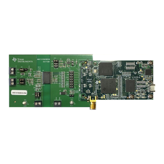
1 Introduction The AMC131M03EVM-PDK is a platform for evaluating the performance of the AMC131M03, which is a 3-channel, simultaneously-sampling, 24-bit, reinforced isolated ΔΣ ADC with integrated DC/DC converter. The evaluation kit includes the AMC131M03EVM board and the precision host interface (PHI) controller board that enables the accompanying computer software to communicate with the ADC over the USB for data capture and analysis. -
Page 5: Evm Analog Interface
49.9 Figure 2-1. Analog Input (Schematic) There are 3 analog input channels for the AMC131M03EVM: channel 0, 1, and 2. Signals can be applied to these channels via terminal blocks J3, J2, and J1, respectively. Channel 0 (AIN0) and Channel 1 (AIN1) contain the same circuitry. This includes a terminal block to apply signals to AIN0P/N and AIN1P/N. -
Page 6: Figure 2-2. Clock Tree (Schematic)
0.1uF ADC_DVDD DGND SN74AUP1G80DCKR DGND PHI_DIGITAL.CLKIN PHI_DIGITAL.MCLK_OUT 33.0 Figure 2-2. Clock Tree (Schematic) Table 2-1. AMC131M03EVM CLKIN Options JP4 Setting CLKIN Source CLKIN Frequency 8.192 MHz 4.096 MHz Configured in graphical user interface (GUI) Open External clock to JP4[5] See data sheet for CLKIN range Note The current build of the GUI does not support the CLKIN signal generated by the PHI. -
Page 7: Digital Interface
EEPROM (over I C). The EEPROM comes pre-programmed with the information required to configure and initialize the AMC131M03EVM platform. When the hardware is initialized, the EEPROM is no longer used. 3.1 SPI Communication The AMC131M03EVM supports limited interface modes as detailed in the AMC131M03 data sheet. The AMC131M03 uses a SPI-compatible interface to configure the device and retrieve conversion data. -
Page 8: Digital Header
AMC131M03 Pin Name Digital Header Pin J5[1], J5[2] J5[3], J5[4] SCLK J5[5], J5[6] DRDY J5[7], J5[8] DOUT J5[9], J5[10] SYNC/ RESET J5[11], J5[12] DGND J5[13], J5[14] AMC131M03 Evaluation Module SBAU402 – APRIL 2023 Submit Document Feedback Copyright © 2023 Texas Instruments Incorporated... -
Page 9: Power Supplies
The PHI provides multiple power-supply options for the EVM, derived from the USB supply of the computer. The EEPROM on the AMC131M03EVM uses a 3.3-V power supply generated directly by the PHI. The low-side analog and digital supply (DVDD) of the ADC uses a 3.3-V power supply provided directly by a low-dropout (LDO) regulator on the PHI. -
Page 10: Amc131M03Evm Initial Setup
Figure 5-1. AMC131M03EVM Jumper Default Settings The default position of the JP4 jumper is across [1-2] at the top. JP4 sets the onboard oscillator frequency to 8.192 MHz, used for the AMC131M03 in high-resolution mode. The default connection for JP1 is to the left [1-2], so that the channel AIN2P of the AMC131M03 is used to convert the signal from the J1 terminal block. -
Page 11: Evm Graphical User Interface (Gui) Software Installation
Figure 5-2. AMC131M03 Software Installation Prompts As a part of the AMC131M03EVM GUI installation, a prompt with a Device Driver Installation (as shown in Figure 5-3) appears on the screen. Click Next to proceed. Figure 5-3. Device Driver Installation Wizard Prompts SBAU402 –... -
Page 12: Figure 5-4. Labview Run-Time Engine Installation
Figure 5-4, if not already installed. Figure 5-4. LabVIEW Run-Time Engine Installation Verify that C:\Program Files (x86)\Texas Instruments\AMC131M03EVM is as shown in Figure 5-5 after these installations. Figure 5-5. AMC131M03EVM GUI Folder Post-Installation AMC131M03 Evaluation Module SBAU402 –... -
Page 13: Amc131M03Evm Operation
AMC131M03EVM Operation 6 AMC131M03EVM Operation The following instructions are a step-by-step guide to connecting the AMC131M03EVM to the computer and evaluating the performance of the AMC131M03: 1. Connect the AMC131M03EVM to the PHI. Install the two screws as indicated in Figure 6-1. -
Page 14: Evm Gui Global Settings For Adc Control
Figure 6-3. EVM GUI Global Input Parameters There are four pages available in the AMC131M03EVM GUI. The information area displays the results of each of the pages. Each of these pages display a different control or measurement of the device. The Register Map Config page is used to read and write to the registers of the device. -
Page 15: Figure 6-4. Clock Setting Dialog
AMC131M03EVM Operation Clock Settings must match the jumper installed on JP4 on the AMC131M03EVM. Select Custom if an external CLKIN clock is provided directly to JP4[5]. Figure 6-4. Clock Setting Dialog The GUI tries to match this frequency as closely as possible by changing the PHI PLL settings, but the achievable frequency can differ from the target value entered. -
Page 16: Register Map Configuration Tool
If interface mode settings are affected by the change in register values, then this change reflects on the left pane immediately. The changes in the register value reflect on the AMC131M03 device on the AMC131M03EVM based on the Update Mode selection, as described in Section 6.1. -
Page 17: Time Domain Display Tool
ADC or drive circuits. The user can trigger a capture of the data of the selected number of samples from the AMC131M03EVM, as per the current interface mode settings indicated in Figure 6-6 by using the Capture button. -
Page 18: Spectral Analysis Tool
24-bit ADC. The None option corresponds to not using a window (or using a rectangular window) and is not recommended. AMC131M03 Evaluation Module SBAU402 – APRIL 2023 Submit Document Feedback Copyright © 2023 Texas Instruments Incorporated... -
Page 19: Histogram Tool
As shown in Figure 6-8, the histogram corresponding to a DC input is displayed on clicking the Capture button. Figure 6-8. Histogram Analysis Tool SBAU402 – APRIL 2023 AMC131M03 Evaluation Module Submit Document Feedback Copyright © 2023 Texas Instruments Incorporated... -
Page 20: Amc131M03Evm Bill Of Materials, Pcb Layout, And Schematic
AMC131M03EVM Bill of Materials, PCB Layout, and Schematic www.ti.com 7 AMC131M03EVM Bill of Materials, PCB Layout, and Schematic 7.1 PCB Layout Figure 7-1 through Figure 7-6 illustrate the AMC131M03EVM PCB layout. Figure 7-1. Top Silkscreen Figure 7-2. Top Layer AMC131M03 Evaluation Module SBAU402 –... -
Page 21: Figure 7-3. Ground Layer - Internal
AMC131M03EVM Bill of Materials, PCB Layout, and Schematic Figure 7-3. Ground Layer - Internal Figure 7-4. Power Layer - Internal SBAU402 – APRIL 2023 AMC131M03 Evaluation Module Submit Document Feedback Copyright © 2023 Texas Instruments Incorporated... -
Page 22: Figure 7-5. Bottom Layer
AMC131M03EVM Bill of Materials, PCB Layout, and Schematic www.ti.com Figure 7-5. Bottom Layer Figure 7-6. Bottom Silkscreen AMC131M03 Evaluation Module SBAU402 – APRIL 2023 Submit Document Feedback Copyright © 2023 Texas Instruments Incorporated... -
Page 23: Schematics
AMC131M03EVM Bill of Materials, PCB Layout, and Schematic 7.2 Schematics Figure 7-7 illustrates the AMC131M03EVM schematics. Digital Interface Clock Tree ADC_DVDD OSC_8.192MHz 33.0 0.1uF CLOCK OUT DGND 100k PHI_DIGITAL.OSC_EN 8.192MHz 1.00k ADC_DIGITAL.CLKIN DGND DGND OSC_EN PHI_DIGITAL.DIN DGND CLKSEL PHI_DIGITAL.CS OSC_4.096MHz... -
Page 24: Bill Of Materials
AMC131M03EVM Bill of Materials, PCB Layout, and Schematic www.ti.com 7.3 Bill of Materials Section 7.3 lists the AMC131M03EVM bill of materials. Table 7-1. AMC131M03EVM Bill of Materials Designator Quantity Value Description Package Reference Part Number Manufacturer CAP, CERM, 100 pF,... -
Page 25: Table 7-1. Amc131M03Evm Bill Of Materials
AMC131M03EVM Bill of Materials, PCB Layout, and Schematic Table 7-1. AMC131M03EVM Bill of Materials (continued) Designator Quantity Value Description Package Reference Part Number Manufacturer Cable, USB-A to micro 102-1092-BL-00100 CnC Tech USB-B, 1 m - Kitting item PHI-EVM Controller... - Page 26 AMC131M03EVM Bill of Materials, PCB Layout, and Schematic www.ti.com Table 7-1. AMC131M03EVM Bill of Materials (continued) Designator Quantity Value Description Package Reference Part Number Manufacturer RES, 10 k, 5%, 0.1 W, Samsung Electro- RC1608J103CS 0603 Mechanics RES, 1.00 k, 1%, 0.1 1.00k...
- Page 27 AMC131M03EVM Bill of Materials, PCB Layout, and Schematic Table 7-1. AMC131M03EVM Bill of Materials (continued) Designator Quantity Value Description Package Reference Part Number Manufacturer RES, 1.00 k, 1%, 0.1 R2, R7 1.00k W, AEC-Q200 Grade 0, CRCW06031K00FKEA Vishay-Dale 0603 SBAU402 –...
- Page 28 STANDARD TERMS FOR EVALUATION MODULES Delivery: TI delivers TI evaluation boards, kits, or modules, including any accompanying demonstration software, components, and/or documentation which may be provided together or separately (collectively, an “EVM” or “EVMs”) to the User (“User”) in accordance with the terms set forth herein.
- Page 29 www.ti.com Regulatory Notices: 3.1 United States 3.1.1 Notice applicable to EVMs not FCC-Approved: FCC NOTICE: This kit is designed to allow product developers to evaluate electronic components, circuitry, or software associated with the kit to determine whether to incorporate such items in a finished product and software developers to write software applications for use with the end product.
- Page 30 www.ti.com Concernant les EVMs avec antennes détachables Conformément à la réglementation d'Industrie Canada, le présent émetteur radio peut fonctionner avec une antenne d'un type et d'un gain maximal (ou inférieur) approuvé pour l'émetteur par Industrie Canada. Dans le but de réduire les risques de brouillage radioélectrique à...
- Page 31 www.ti.com EVM Use Restrictions and Warnings: 4.1 EVMS ARE NOT FOR USE IN FUNCTIONAL SAFETY AND/OR SAFETY CRITICAL EVALUATIONS, INCLUDING BUT NOT LIMITED TO EVALUATIONS OF LIFE SUPPORT APPLICATIONS. 4.2 User must read and apply the user guide and other available documentation provided by TI regarding the EVM prior to handling or using the EVM, including without limitation any warning or restriction notices.
- Page 32 Notwithstanding the foregoing, any judgment may be enforced in any United States or foreign court, and TI may seek injunctive relief in any United States or foreign court. Mailing Address: Texas Instruments, Post Office Box 655303, Dallas, Texas 75265 Copyright © 2023, Texas Instruments Incorporated...
- Page 33 TI products. TI’s provision of these resources does not expand or otherwise alter TI’s applicable warranties or warranty disclaimers for TI products. TI objects to and rejects any additional or different terms you may have proposed. IMPORTANT NOTICE Mailing Address: Texas Instruments, Post Office Box 655303, Dallas, Texas 75265 Copyright © 2023, Texas Instruments Incorporated...
Need help?
Do you have a question about the AMC131M03EVM and is the answer not in the manual?
Questions and answers