Table of Contents
Advertisement
Quick Links
This user's guide describes the characteristics, operation, and use of the AMC7832 evaluation module
(EVM). This user's guide also discusses the proper setup and configuration of software and hardware and
reviews various aspects of program operation. A complete circuit description, schematic diagram, and bill
of materials are also included.
......................................................................................................................
1
1.1
1.2
2
2.1
2.2
2.3
3
3.1
3.2
4
4.1
4.2
4.3
4.4
4.5
4.6
4.7
5
5.1
5.2
6
6.1
6.2
6.3
1
AMC7832EVM Hardware Setup
2
3
4
5
6
7
8
9
10
11
Microsoft, Windows are registered trademarks of Microsoft Corporation.
SLAU544A - February 2014 - Revised September 2016
Submit Documentation Feedback
Contents
.......................................................................................
...................................................................................
...........................................................................................
............................................................................................
.............................................................................
.......................................................................................
..................................................................................
..........................................................................................
..........................................................................
...................................................................................................
...................................................................................................
..................................................................................................
......................................................................................
...........................................................................
..............................................................................
...........................................................................................
................................................................................
......................................................................
.........................................................................
List of Figures
...........................................................................................
.....................................................................................
..................................................................................
.........................................................................................
.................................................................................................
.............................................................................................
.........................................................................................
.....................................................................................................
............................................................................................
Copyright © 2014-2016, Texas Instruments Incorporated
SLAU544A - February 2014 - Revised September 2016
AMC7832EVM User's Guide
...................................................................
.....................................................
..............................................................
...............................................................
............................................................
................................................................
..........................................................
AMC7832EVM User's Guide
User's Guide
3
3
3
4
4
5
6
7
7
7
9
9
9
10
10
11
11
12
13
13
14
22
22
24
25
4
4
6
7
8
10
10
13
13
14
14
1
Advertisement
Table of Contents

Subscribe to Our Youtube Channel
Related Manuals for Texas Instruments AMC7832EVM


Summary of Contents for Texas Instruments AMC7832EVM
-
Page 1: Table Of Contents
AMC7832 Test Board Block Diagram .................. SDM-USB-DIG Platform Block Diagram ..................AMC7832EVM Installer Directory ....................AMC7832EVM Install Path ..............Typical Hardware Connections on the AMC7832EVM ............Confirmation of SDM-USB-DIG Platform Driver Installation ..................... AMC7832EVM GUI Location ..................AMC7832EVM GUI – Power On ..................... - Page 2 Contents of AMC7832EVM Kit ..................... Related Documentation ......................J6 Signal Definition ....................Default Jumper Settings ..............AMC7832EVM Jumper and Shunt Resistor Settings ................AMC7832EVM ADC Signal Connections ................AMC7832EVM DAC Signal Connections ................AMC7832EVM DAC Range Connections .................. AMC7832EVM GPIO Signal Definition ......................
-
Page 3: Overview
The following document provides information regarding TI integrated circuits used in the assembly of the AMC7832EVM. This user's guide is available from the TI website under literature number SLAU544. A letter appended to the literature number corresponds to the document revision that is current at the time of the writing of this document. -
Page 4: Amc7832Evm Hardware Setup
SDM-USB- Figure 1. AMC7832EVM Hardware Setup Theory of Operation for AMC7832 Hardware A block diagram of the AMC7832EVM test board is displayed in Figure 2. The EVM board provides testpoints for the supplies, internal reference, ground connections, SPI inputs, ADC inputs, and DAC outputs. -
Page 5: Signal Definitions Of J6 (10-Pin Male Connector Socket)
Signal Definitions of J6 (10-Pin Male Connector Socket) The AMC7832EVM includes a 20-pin connector socket used to communicate between the EVM and the SDM-USB-DIG platform. Although the I C pins are brought out to the J12 header, the I C communication lines (I2C_SCL and I2C_SDA) are not used. -
Page 6: Theory Of Operation For Sdm-Usb-Dig Platform
(Hi-Z, 3.3 V, or 5 V) USB +5.0 V Power Switched Power Switching +3.3 V Figure 3. SDM-USB-DIG Platform Block Diagram AMC7832EVM User’s Guide SLAU544A – February 2014 – Revised September 2016 Submit Documentation Feedback Copyright © 2014–2016, Texas Instruments Incorporated... -
Page 7: Amc7832Evm Software Setup
C:\Program Files\AMC7832EVM. The software installation automatically copies the required drivers for the SDM-USB-DIG and AMC7832EVM to the PC. After the software is installed, connecting the SDM-USB-DIG to a USB port may launch a driver installation dialog. Choose the ‘Install this driver software anyway’... -
Page 8: Amc7832Evm Install Path
AMC7832EVM Software Setup www.ti.com Figure 5. AMC7832EVM Install Path AMC7832EVM User’s Guide SLAU544A – February 2014 – Revised September 2016 Submit Documentation Feedback Copyright © 2014–2016, Texas Instruments Incorporated... -
Page 9: Amc7832Evm Hardware Overview
Table 4. The table also displays the default configurations of all jumper connections on the AMC7832EVM. Connect the USB extender cable from the SDM-USB-DIG to the PC, and the +24- V wall adapter to the J1 terminal. Table 4. Default Jumper Settings... -
Page 10: Connecting The Usb Cable To The Sdm-Usb-Dig
This section describes the various power configurations that can be used by the EVM. The AMC7832EVM provides terminal blocks for external supplies as well as (optional) onboard power conditioning to convert a 24-V supply into a +12-V, -12-V, and 5-V supply. Jumpers JP3 and JP6 can be configured to use external supplies through the J2 and J11 terminal blocks or the jumpers can be configured for the onboard regulated supplies. -
Page 11: Adc Signal Pins
Additionally, IOV is supplied by the SDM-USB-DIG, but can be externally sourced by setting the JP6 jumper, and connecting an external source to the J11 terminal block. Table 5. AMC7832EVM Jumper and Shunt Resistor Settings SIGNAL JUMPER DEFAULT POSITION... -
Page 12: Gpio Signal Pins
AMC7832EVM Hardware Overview www.ti.com Table 7. AMC7832EVM DAC Signal Connections NAME CONNECTOR DESCRIPTION DACC0 J9-1 DAC-C0 output DACC1 J9-3 DAC-C1 output DACD2 J10-1 DAC-D2 output DACD3 J10-3 DAC-D3 output DACD4 J10-5 DAC-D4 output DACD5 J10-7 DAC-D5 output DACB6 J7-1 DAC-B6 output... -
Page 13: Amc7832Evm Software Overview
USB extender cable is properly connected to both the SDM-USB-DIG and PC, and relaunch the GUI. This issue can also occur if the CDC driver is installed incorrectly. The AMC7832EVM software may need to be reinstalled. -
Page 14: Amc7832Evm Software Features
5.2.2 AMC7832EVM Low Level Configuration Page The AMC7832EVM features a register map page that allows access to low-level communication by directly writing to and reading from the AMC7832 device’s registers. Selecting a register on the Register Map list presents a description of the values in that register and also displays information such as the register’s address, default value, size, and current value. - Page 15 Enable Internal Reference Buffer and Power ADC Block. This sequence is shown in Figure Figure 13. ADC Block Activation Sequence SLAU544A – February 2014 – Revised September 2016 AMC7832EVM User’s Guide Submit Documentation Feedback Copyright © 2014–2016, Texas Instruments Incorporated...
- Page 16 To fully activate the DAC block, set the Enable Reference Block. To set the DAC channels individually, select their respective checkbox in the Power DACs column (see Figure 15). AMC7832EVM User’s Guide SLAU544A – February 2014 – Revised September 2016 Submit Documentation Feedback Copyright © 2014–2016, Texas Instruments Incorporated...
- Page 17 C and D. The DAC voltage range jumper settings are displayed in Table 8. Ensure that the AMC7832EVM board is powered off before selecting different jumper positions. The DAC page also displays two input fields in the Program Values column (see Figure 16).
- Page 18 Figure 18 displays the ALARMS page of the AMC7832EVM. The page displays the name of each alarm, shown in the Alarm Name column, and provides information such as the value, high limit, low limit, and alarm status, along with other additional options.
- Page 19 The ALARMIN-ALR checkbox gives the user the ability to clear the DACs with an active low input signal through GPIO0. Just as with GPIO1, GPIO0 must be configured for ALARMIN for this function to take effect. SLAU544A – February 2014 – Revised September 2016 AMC7832EVM User’s Guide Submit Documentation Feedback Copyright © 2014–2016, Texas Instruments Incorporated...
- Page 20 ALARMIN pin, which then creates an active low signal on the ALARMOUT pin. These functions need to be set in the GPIO configuration register, which is available for configuration in the GPIO page of the AMC7832EVM GUI. 5.2.6...
- Page 21 AMC7832EVM Software Overview www.ti.com Figure 23. GPIO Write or Read SLAU544A – February 2014 – Revised September 2016 AMC7832EVM User’s Guide Submit Documentation Feedback Copyright © 2014–2016, Texas Instruments Incorporated...
-
Page 22: Amc7832Evm Documentation
AMC7832EVM Documentation This section contains the schematic diagrams and complete bill of materials for the AMC7832EVM. Documentation information for the SDM-USB- DIG platform can be found in the SDM-USB-DIG Platform User’s Guide, SBOU136, available at the TI website at www.ti.com. - Page 23 THERM1 Vdut I2C_CLK 10 F 0.1 F I2C_SDA TP19 TP20 TP21 TP22 TP23 Vdut SCLK Vdut Figure 24. Board Schematic SLAU544A – February 2014 – Revised September 2016 AMC7832EVM User’s Guide Submit Documentation Feedback Copyright © 2014–2016, Texas Instruments Incorporated...
-
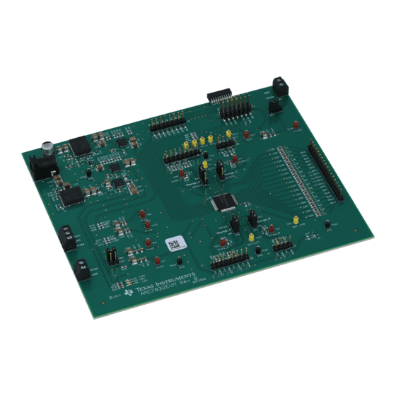
Page 24: Amc7832Evm Pcb Components Layout
AMC7832EVM Documentation www.ti.com AMC7832EVM PCB Components Layout Figure 25 shows the layout of the components for the AMC7832EVM board. Figure 25. AMC7832EVM PCB Components Layout AMC7832EVM User’s Guide SLAU544A – February 2014 – Revised September 2016 Submit Documentation Feedback Copyright © 2014–2016, Texas Instruments Incorporated... -
Page 25: Amc7832 Test Board Bill Of Materials
RES, 174k ohm, 1%, 0.1W, 0603 Vishay-Dale CRCW0603174KFKEA RES, 178k ohm, 1%, 0.1W, 0603 Vishay-Dale CRCW0603178KFKEA RES, 24.9k ohm, 1%, 0.1W, 0603 Vishay-Dale CRCW060324K9FKEA SLAU544A – February 2014 – Revised September 2016 AMC7832EVM User’s Guide Submit Documentation Feedback Copyright © 2014–2016, Texas Instruments Incorporated... - Page 26 Shunt, 100mil, Gold plated, Black 969102-0000-DA SH-JP4, SH-JP5, SH-JP6 H1, H2, H3, H4 Bumpon, Hemisphere, 0.44 X 0.20, Clear SJ-5303 (CLEAR) AMC7832EVM User’s Guide SLAU544A – February 2014 – Revised September 2016 Submit Documentation Feedback Copyright © 2014–2016, Texas Instruments Incorporated...
- Page 27 On the second page of the schematic; removed 'DNI' label and added '0 Ω' label to R55 and R73, added 'DNI' label to ..........................R48 and R75........................• Updated Figure SLAU544A – February 2014 – Revised September 2016 Revision History Submit Documentation Feedback Copyright © 2014–2016, Texas Instruments Incorporated...
- Page 28 STANDARD TERMS AND CONDITIONS FOR EVALUATION MODULES Delivery: TI delivers TI evaluation boards, kits, or modules, including any accompanying demonstration software, components, or documentation (collectively, an “EVM” or “EVMs”) to the User (“User”) in accordance with the terms and conditions set forth herein. Acceptance of the EVM is expressly subject to the following terms and conditions.
- Page 29 FCC Interference Statement for Class B EVM devices NOTE: This equipment has been tested and found to comply with the limits for a Class B digital device, pursuant to part 15 of the FCC Rules. These limits are designed to provide reasonable protection against harmful interference in a residential installation.
- Page 30 【無線電波を送信する製品の開発キットをお使いになる際の注意事項】 開発キットの中には技術基準適合証明を受けて いないものがあります。 技術適合証明を受けていないもののご使用に際しては、電波法遵守のため、以下のいずれかの 措置を取っていただく必要がありますのでご注意ください。 1. 電波法施行規則第6条第1項第1号に基づく平成18年3月28日総務省告示第173号で定められた電波暗室等の試験設備でご使用 いただく。 2. 実験局の免許を取得後ご使用いただく。 3. 技術基準適合証明を取得後ご使用いただく。 なお、本製品は、上記の「ご使用にあたっての注意」を譲渡先、移転先に通知しない限り、譲渡、移転できないものとします。 上記を遵守頂けない場合は、電波法の罰則が適用される可能性があることをご留意ください。 日本テキサス・イ ンスツルメンツ株式会社 東京都新宿区西新宿6丁目24番1号 西新宿三井ビル 3.3.3 Notice for EVMs for Power Line Communication: Please see http://www.tij.co.jp/lsds/ti_ja/general/eStore/notice_02.page 電力線搬送波通信についての開発キットをお使いになる際の注意事項については、次のところをご覧くださ い。http://www.tij.co.jp/lsds/ti_ja/general/eStore/notice_02.page SPACER EVM Use Restrictions and Warnings: 4.1 EVMS ARE NOT FOR USE IN FUNCTIONAL SAFETY AND/OR SAFETY CRITICAL EVALUATIONS, INCLUDING BUT NOT LIMITED TO EVALUATIONS OF LIFE SUPPORT APPLICATIONS.
- Page 31 Notwithstanding the foregoing, any judgment may be enforced in any United States or foreign court, and TI may seek injunctive relief in any United States or foreign court. Mailing Address: Texas Instruments, Post Office Box 655303, Dallas, Texas 75265 Copyright © 2015, Texas Instruments Incorporated...
- Page 32 IMPORTANT NOTICE Texas Instruments Incorporated and its subsidiaries (TI) reserve the right to make corrections, enhancements, improvements and other changes to its semiconductor products and services per JESD46, latest issue, and to discontinue any product or service per JESD48, latest issue.
- Page 33 Mouser Electronics Authorized Distributor Click to View Pricing, Inventory, Delivery & Lifecycle Information: Texas Instruments AMC7832EVM...
Need help?
Do you have a question about the AMC7832EVM and is the answer not in the manual?
Questions and answers