Circontrol Raption 150 Series Quick Start Installation Manual
Hide thumbs
Also See for Raption 150 Series:
- Installation manual (68 pages) ,
- Service manual (110 pages) ,
- User manual (120 pages)
Table of Contents
Advertisement
Quick Links
Advertisement
Table of Contents

Related Manuals for Circontrol Raption 150 Series


Summary of Contents for Circontrol Raption 150 Series
- Page 1 Raption 150 Series Quick Start Installation Manual...
- Page 2 C O P Y R I G H T I N F O R M AT I O N This document is copyrighted, 2021 by Circontrol, S.A. All rights are reserved. Circontrol, S.A. reserves the right to make improvements to the products described in this manual at any time without notice.
-
Page 3: Table Of Contents
Here’s your guide to install Raption 150 1 — So, Hello! 2 — Before the installation A - Important safety instructions B - What's included 3 — Dimensions and overview A - Dispenser B - Power unit C - Placing 4 —... -
Page 4: So, Hello
It is mandatory to follow the basic security information supplied in this manual to ensure safe and proper installation. Failure to follow safety instructions may involve personal injury, equipment damage and danger of death. CIRCONTROL is not responsible for events arising from such breach. -
Page 5: Before The Installation
• Do not use this unit for anything other close...). than electric vehicle charging modes are expected in IEC 61851. • Use only Circontrol supplied spare parts. • Do not modify this unit. If modified, CIRCONTROL will reject all • Do not use this unit if the enclosure... -
Page 6: What's Included
Raption 150 Quick Start Installation Manual What’s included Eyebolt Acces door Key CirCarLife RFID Charge Point Mifare Card Installation Dispenser Power Unit Manual Foundation Kit Foundation Kit... -
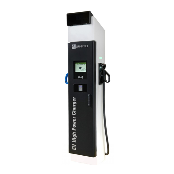
Page 7: Dimensions And Overview
Dimensions and Overview Dispenser Units specified in millimeters 1 — Cover 2 — Courtesy Lights 3 — Screen 4 — CCS/CHA plug 5 — Emergency button 6 — RFID Reader 7 — Locking handle 8 — Decorative Front panel 9 — Antenna 10 —... -
Page 8: Power Unit
Raption 150 Quick Start Installation Manual Power Unit 1000 Units specified in millimeters 1- Cover 2- Unit air inlet 3- Locking 4- Locking handle 5- Rear door handle 6- Decorative 7- Eyebolts 8- Unit air 9- Front door 10-Decorative Rear panel outlet Front panel... -
Page 9: C Placing
Placing In order to place the Charge Point in its final place, please follow next steps: R E M O V I N G T H E C H A R G E P O I N T F R O M PA L L E T The Charge Point is mounted on a pallet so as to do a safe transport. - Page 10 Raption 150 Quick Start Installation Manual P L AC I N G T H E P O W E R U N I T I N T H E F I N A L L O C AT I O N Once the Power Unit is free from the pallet, there are two options to move the charger.
-
Page 11: Installation
Installation When installing the Dispenser or Power Unit, respect the minimum distances space for maintenance and safety reasons. • Do not install near areas where water or fluids can penetrate into the unit. • Do not install on unstable terrain. •... -
Page 12: C Dispenser Foundation
Raption 150 Quick Start Installation Manual Dispenser foundation The foundation kit with a mounting template is provided to ensure the distances between the foundation bolts. Place the foundation bolts into the templates using provided nuts with the help of a 24mm open-end wrench. - Page 13 C O N C R E T E B A S E M E N T F O R D I S P E N S E R • Once the kit is assembled, it must be placed in the ground. If the Dispenser has to be installed outside and there is no limitation of depth, is recommended to make a concrete base.
- Page 14 Raption 150 Quick Start Installation Manual F O U N DAT I O N M E A S U R E M E N T S F O R D I S P E N S E R ORIENTATIONAL FOUNDATIONS FOR RAPTION 150 TYPE OF TERRAIN FOUNDATION SIZE COMMENTS...
-
Page 15: D Power Unit Foundation
Power Unit foundation • Place the foundation bolts into the templates using provided nuts with the help of a 24mm open-end wrench. Take into consideration the following measures. • Take in mind the disposition of the supply of the power unit and the cables that go to the dispenser. - Page 16 Raption 150 Quick Start Installation Manual C O N C R E T E B A S E M E N T F O R P O W E R U N I T • Once the kit is assembled, it must be placed in the ground. If the Power Unit has to be installed outside and there is no limitation of depth, is recommended to make a concrete base.
- Page 17 F O U N DAT I O N M E A S U R E M E N T S F O R P OW E R U N I T ORIENTATIONAL FOUNDATIONS FOR RAPTION 150 TYPE OF TERRAIN FOUNDATION SIZE COMMENTS (kg/cm (Az x Bz x Hz) cm...
-
Page 18: Wiring
Raption 150 Quick Start Installation Manual Wiring Regardless of the electrical characteristics of the power line, be sure to supply to the Charge Point with the necessary electrical features indicated at the unit characteristics label, understood as, supply voltage, grid frequency and required apparent power. In order to guarantee the total protection of the users and the installation (power supply line included) in front of any electrical hazard, it is mandatory to install a main circuit breaker (MCB) and a residual current device (RCD) upstream of the charger. - Page 19 DC #1 DC #2 L + N + PE ETHERNET CABLE - DC#1: CHA power cables. - DC#2: CCS power cables. - PE: earth cable for the Dispenser. - L+N+PE: supply for the Dispenser electronics. - Ethernet Cable: For communications between Power Unit and Dispenser.
-
Page 20: A Power Unit
In the case of not using this metal plate and any damage to internal components arises due to the entry of dirt, animals or any other external element, Circontrol will reject the warranty of the unit. Steps: 1- Locate the power input entrance in the bottom of the Power Unit. Accessed from the back door. - Page 21 3 - Power connection for the Power Unit - Connecting supply cables - : to the dispenser Notes: 1- Use the M10 screw and washer provided in order to connect the electric terminals. The maximum tightening torque has to be 18Nm 2- Use a M10 metallic electric terminal aligned with the required cable cross section according with the power of the Charge Point (Max.
- Page 22 In the case of not using this metal plate and any damage to internal components arises due to the entry of dirt, animals or any other external element, Circontrol will reject the warranty of the unit. Steps: 1- Locate the power output in the Power Unit in the bottom of the Power Unit. Accessed from the front door.
- Page 23 5 - Power output connection from Power Unit - Connecting Cables - : Locate the connection points in the Power Unit. ETHERNET L1 N PE...
- Page 24 Raption 150 Quick Start Installation Manual 18 Nm 18 Nm CCS - CHA - 18 Nm CCS + 18 Nm CHA + Metal plate power unit to dispenser...
-
Page 25: B - Dispenser
In order to make a secure cable installation is necessary to use the metal plate provided. In the case of not using this metal plate and any damage to internal components arises due to the entry of dirt, animals or any other external element, Circontrol will reject the warranty of the unit. - Page 26 Raption 150 Quick Start Installation Manual 3 - Power input connection to Dispenser - connecting cables - : Locate the connection points in the Dispenser. L1 N PE ETHERNET...
- Page 27 Note: Use the M10 screw in order to connect the electric terminals. The recommended tightening torque has to be 23 CHA + CHA- CCS + CCS -...
- Page 28 Raption 150 Quick Start Installation Manual Wiring section WIRING CROSS SECTIONAL AREA RECOMMENDATIONS Maximum cross Minimum cross From Cables sectional area sectional area* supported 2x DC + Dispenser 95~120mm 120mm 2x DC - Dispenser 1x PE 50mm 120mm Dispenser L + N + PE 2,5mm 2,5mm L1+ L2 + L3 + N + PE...
-
Page 29: Last Steps
In order to use and configure the Charge Point there is an User Manual. It is necessary to be registered with the Circontrol Expert Area: http://expertarea.circontrol.com Note: ask to the Circontrol PS-Support department in order to register with the Circontrol Expert Area: support@circontrol.com... - Page 30 Raption 150 Quick Start Installation Manual...
- Page 32 CIRCONTROL Raption 150 QUICK START INSTALLATION MANUAL A comprehensive guide on how to install and verify your Raption 150 Charging Station. V1.0, August edition 2021 R417 CIRCONTROL S.A. - ALL RIGHTS RESERVED...
Need help?
Do you have a question about the Raption 150 Series and is the answer not in the manual?
Questions and answers