Table of Contents
Advertisement
Quick Links
www.ti.com
User's Guide
TPS389006Q1EVM Multichannel Voltage Supervisor with
2
I
C
This user's guide describes the operational use of the TPS389006Q1EVM evaluation module (EVM) as a
reference design for engineering demonstration and evaluation of the
2
and Undervoltage I
C Programmable Voltage Supervisor and
bill of materials (BOM), assembly drawing, and top and bottom board layouts.
1
Introduction.............................................................................................................................................................................3
Documentation......................................................................................................................................................4
Applications..............................................................................................................................................4
2 Schematic, Bill of Materials, and Layout..............................................................................................................................
Schematic..........................................................................................................................................6
2.2 TPS389006Q1EVM Bill of Materials..................................................................................................................................
2.3 Layout and Component Placement..................................................................................................................................
2.4
Layout...............................................................................................................................................................................11
3 EVM Connectors...................................................................................................................................................................
Points...............................................................................................................................................................13
Jumpers...................................................................................................................................................................14
Operation....................................................................................................................................................15
4.1 Setup and GUI Installations.............................................................................................................................................
4.2 Quick Start to TPS389006Q1EVM GUI...........................................................................................................................
4.3 Example Operation of TPS389xxx-Q1.............................................................................................................................
5 Revision History...................................................................................................................................................................
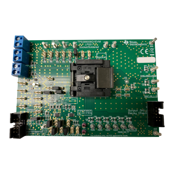
Figure 1-1. TPS389006Q1EVM Board Top.................................................................................................................................
Figure 2-1. TPS389006Q1EVM Main Schematic........................................................................................................................
Figure 2-3. Component Placement-Top Assembly..................................................................................................................
Layout-Top.............................................................................................................................................................11
Figure 2-6. Layout-Bottom.......................................................................................................................................................
Layer.................................................................................................................................................................12
Figure 2-8. Bottom Layer...........................................................................................................................................................
Mask......................................................................................................................................................12
Figure 2-10. Bottom Solder Mask..............................................................................................................................................
Figure 3-1. TPS389006Q1EVM Jumper Locations...................................................................................................................
Figure 4-2. Setup License Agreement Window.........................................................................................................................
Figure 4-3. Setup Destination Window......................................................................................................................................
Figure 4-5. Setup Window - Additional Tasks............................................................................................................................
Figure 4-6. Setup Installation Window.......................................................................................................................................
Figure 4-7. Installation Complete Window.................................................................................................................................
Figure 4-8. Fusion Welcome Window........................................................................................................................................
Window...............................................................................................................................................21
SNVU785A - FEBRUARY 2022 - REVISED MAY 2023
Submit Document Feedback
ABSTRACT
Table of Contents
List of Figures
Bottom............................................................................................................................4
2
C Schematic with Buffers.......................................................................................................
Assembly.............................................................................................................11
Description...........................................................................................................16
Selection.....................................................................................................................18
Copyright © 2023 Texas Instruments Incorporated
TPS389006-Q1 Multichannel Overvoltage
Monitor. This guide contains the EVM schematic,
TPS389006Q1EVM Multichannel Voltage Supervisor with I
Table of Contents
5
8
11
13
16
20
25
27
3
6
7
11
11
12
12
14
17
17
18
19
19
20
2
C
1
Advertisement
Table of Contents

Related Manuals for Texas Instruments TPS389006Q1EVM


Summary of Contents for Texas Instruments TPS389006Q1EVM
-
Page 1: Table Of Contents
Table of Contents User's Guide TPS389006Q1EVM Multichannel Voltage Supervisor with ABSTRACT This user's guide describes the operational use of the TPS389006Q1EVM evaluation module (EVM) as a reference design for engineering demonstration and evaluation of the TPS389006-Q1 Multichannel Overvoltage and Undervoltage I C Programmable Voltage Supervisor and Monitor. - Page 2 Figure 4-11. Fusion Scan Window - Scanning for TPS389006Q1EVM..................Figure 4-12. Fusion Scan Window - Scan for TPS389006Q1EVM Completed................. Figure 4-13. Fusion Digital Power Device GUI - TPS389006Q1EVM (screenshot #1)............. Figure 4-14. Fusion Digital Power Device GUI - TPS389006Q1EVM (screenshot #2).............
-
Page 3: Introduction
Monitor. Test points are provided to give the user additional access, if needed, for oscilloscope or multi-meter measurements. The TPS389006Q1EVM comes pre-populated with TPS38900603NRTERQ1. This IC variant is configured for six integrated multichannel window inputs to monitor six distinct input voltage rails with two remote sense pins. -
Page 4: Related Documentation
1.2 TPS389006-Q1 Applications • Advanced Driver Assistance System (ADAS) • Sensor fusion • Medical robotics • Industrial robotics TPS389006Q1EVM Multichannel Voltage Supervisor with I SNVU785A – FEBRUARY 2022 – REVISED MAY 2023 Submit Document Feedback Copyright © 2023 Texas Instruments Incorporated... -
Page 5: Schematic, Bill Of Materials, And Layout
Schematic, Bill of Materials, and Layout 2 Schematic, Bill of Materials, and Layout This section provides a detailed description of the TPS389006Q1EVM schematic, bill of materials (BOM), and layout. SNVU785A – FEBRUARY 2022 – REVISED MAY 2023 TPS389006Q1EVM Multichannel Voltage Supervisor with I Submit Document Feedback Copyright ©... -
Page 6: Tps389006Q1Evm Schematic
RCS06031R00FKEA 1.0k VAUX VAUX TLV4082DRYR VAUX 150060SS75000 Super Red TLV4082DRYR RCS06031R00FKEA 1.0k Figure 2-1. TPS389006Q1EVM Main Schematic TPS389006Q1EVM Multichannel Voltage Supervisor with I2C SNVU785A – FEBRUARY 2022 – REVISED MAY 2023 Submit Document Feedback Copyright © 2023 Texas Instruments Incorporated... -
Page 7: Figure 2-2. Tps389006Q1Evm I 2 C Schematic With Buffers
Schematic, Bill of Materials, and Layout Figure 2-2. TPS389006Q1EVM I C Schematic with Buffers SNVU785A – FEBRUARY 2022 – REVISED MAY 2023 TPS389006Q1EVM Multichannel Voltage Supervisor with I2C Submit Document Feedback Copyright © 2023 Texas Instruments Incorporated... -
Page 8: Tps389006Q1Evm Bill Of Materials
THRU HOLE WITH CENTER GND J8, J18 Shrouded Header (shrouded), 100mil, 5x2, 5103308-1 TE Connectivity Header Gold, TH Shrouded header TPS389006Q1EVM Multichannel Voltage Supervisor with I SNVU785A – FEBRUARY 2022 – REVISED MAY 2023 Submit Document Feedback Copyright © 2023 Texas Instruments Incorporated... - Page 9 Comparator with Integrated Reference U5, U6 Automotive, Level-Shifting I C Bus VSSOP-8 TCA9517DGKRQ1 Repeater, DGK0008A (VSSOP-8) (DGK0008A) SNVU785A – FEBRUARY 2022 – REVISED MAY 2023 TPS389006Q1EVM Multichannel Voltage Supervisor with I Submit Document Feedback Copyright © 2023 Texas Instruments Incorporated...
- Page 10 PART NUMBER MANUFACTURER REFERENCE FID1, FID2, FID3 Fiducial mark. There is nothing to buy Fiducial or mount. TPS389006Q1EVM Multichannel Voltage Supervisor with I SNVU785A – FEBRUARY 2022 – REVISED MAY 2023 Submit Document Feedback Copyright © 2023 Texas Instruments Incorporated...
-
Page 11: Layout And Component Placement
2.4 Layout Figure 2-3. Component Placement—Top Assembly Figure 2-4. Component Placement—Bottom Assembly Figure 2-6. Layout—Bottom Figure 2-5. Layout—Top SNVU785A – FEBRUARY 2022 – REVISED MAY 2023 TPS389006Q1EVM Multichannel Voltage Supervisor with I Submit Document Feedback Copyright © 2023 Texas Instruments Incorporated... -
Page 12: Figure 2-7. Top Layer
Figure 2-7. Top Layer Figure 2-8. Bottom Layer Figure 2-10. Bottom Solder Mask Figure 2-9. Top Solder Mask TPS389006Q1EVM Multichannel Voltage Supervisor with I SNVU785A – FEBRUARY 2022 – REVISED MAY 2023 Submit Document Feedback Copyright © 2023 Texas Instruments Incorporated... -
Page 13: Evm Connectors
Allows the user to apply a power supply voltage that is not provided PEXT External power supply from the EVM GND for EVM GND for EVM SNVU785A – FEBRUARY 2022 – REVISED MAY 2023 TPS389006Q1EVM Multichannel Voltage Supervisor with I Submit Document Feedback Copyright © 2023 Texas Instruments Incorporated... -
Page 14: Evm Jumpers
EVM Connectors www.ti.com 3.2 EVM Jumpers Table 3-2 lists the jumpers on the TPS389006Q1EVM. As ordered, the EVM has thirty-five (35) jumpers installed. Figure 3-1 is provided as visual aid. Table 3-2. List of On-board Jumpers JUMPER JUMPER CONFIGUATION DESCRIPTION... -
Page 15: Evm Setup And Operation
The TPS389006Q1EVM is designed to be daisy-chain where the primary board is connected to the USB to GPIO connector (J18) and the output connector (J8) provides VDD, VAUX, SYNC, SCL, SDA, NIRQ, and GND to the (J18) connector of the secondary board through a 10-pin ribbon cable. -
Page 16: Setup And Gui Installations
6. Connect the TI's USB Interface Adapter to the computer's USB port. 7. Connect any voltage supply rail that needs monitoring to any of the voltage monitoring inputs (MON1 - MON8). 8. The description of the TPS389006Q1EVM connections can be found in Figure 4-1. -
Page 17: Figure 4-2. Setup License Agreement Window
EVM Setup and Operation 4.1.2 TPS389006Q1EVM Software Setup Follow the steps below for TPS389006Q1EVM GUI software installation: 1. Download the Fusion Digital Power Designer Platform GUI for TPS389006Q1EVM. 2. Open the downloaded file. 3. In the Welcome Wizard window, click Next. -
Page 18: Figure 4-4. Setup Window - Start Menu Selection
Figure 4-4. Setup Window - Start Menu Selection 7. There is no need to install additional options for this EVM. Click Next. Figure 4-5. Setup Window - Additional Tasks TPS389006Q1EVM Multichannel Voltage Supervisor with I SNVU785A – FEBRUARY 2022 – REVISED MAY 2023 Submit Document Feedback... -
Page 19: Figure 4-6. Setup Installation Window
9. Click on Finish to complete the installation setup and launch the software. Figure 4-7. Installation Complete Window SNVU785A – FEBRUARY 2022 – REVISED MAY 2023 TPS389006Q1EVM Multichannel Voltage Supervisor with I Submit Document Feedback Copyright © 2023 Texas Instruments Incorporated... -
Page 20: Quick Start To Tps389006Q1Evm Gui
Section 4.1 have been completed. Feel free to skip the GUI installation if the Fusion Digital Power Designer for TPS389006Q1EVM GUI has been installed already. 2. Power the EVM by turning on the power supply. Note that the voltage and current limits at the power supply is set at 3.3 V and 10 mA. -
Page 21: Figure 4-9. Fusion Scan Window
5. Click on Change Scan Mode to select TPS389xxx and then click OK. Figure 4-9. Fusion Scan Window Figure 4-10. Fusion Scan Selection Window SNVU785A – FEBRUARY 2022 – REVISED MAY 2023 TPS389006Q1EVM Multichannel Voltage Supervisor with I Submit Document Feedback Copyright © 2023 Texas Instruments Incorporated... -
Page 22: Figure 4-11. Fusion Scan Window - Scanning For Tps389006Q1Evm
EVM Setup and Operation www.ti.com 6. Scan for the TPS389006Q1EVM by clicking on Scan for TPS389xxx on top left of the window. Figure 4-11. Fusion Scan Window - Scanning for TPS389006Q1EVM 7. Once the EVM is discovered, select Click to Configure. -
Page 23: Figure 4-13. Fusion Digital Power Device Gui - Tps389006Q1Evm (Screenshot #1)
TPS389006-Q1 appears as shown below. The GUI screenshot shows the General Config, Sequencing, Clear/Reset, Telmetry, and Polling (Plotting the monitored voltage rails) sub-windows. Figure 4-13. Fusion Digital Power Device GUI - TPS389006Q1EVM (screenshot #1) 9. The GUI screenshot below continues to show the additional sub-windows that are in the GUI for the TPS389006-Q1. -
Page 24: Figure 4-15. Fusion Digital Power Device Gui - Tps389006Q1Evm (Screenshot #3)
10. The last GUI screenshot below shows the last five registers in the Status Registers sub-window. Figure 4-15. Fusion Digital Power Device GUI - TPS389006Q1EVM (screenshot #3) TPS389006Q1EVM Multichannel Voltage Supervisor with I SNVU785A – FEBRUARY 2022 – REVISED MAY 2023 Submit Document Feedback Copyright ©... -
Page 25: Example Operation Of Tps389Xxx-Q1
4-16, are set on the TPS389006Q1EVM. 4. Ground turret (MON7/RS_1/2). 5. Apply 0.8 V to MON1, 1.0 V to MON2, 1.8 V to MON3, 3.3 V to MON4 to the turrets of TPS389006Q1EVM. 6. Final Connections must look similar to Figure 4-16. -
Page 26: Figure 4-17. Tps389006Q1Evm Gui Setup For Monitoring Four Voltage Supply
14. Steps 8 through 13 refers to Figure 4-17 below. Figure 4-17. TPS389006Q1EVM GUI Setup for Monitoring Four Voltage Supply Rails TPS389006Q1EVM Multichannel Voltage Supervisor with I SNVU785A – FEBRUARY 2022 – REVISED MAY 2023 Submit Document Feedback... -
Page 27: Revision History
5 Revision History Changes from Revision * (February 2022) to Revision A (May 2023) Page • Changed the OPN to TPS389006004RTERQ1 from TPS389006Q1 in TPS389006Q1EVM Main Schematic • Changed the OPN to TPS389006004RTERQ1 from TPS389006Q1 in Bill of Materials table......8 SNVU785A –... - Page 28 STANDARD TERMS FOR EVALUATION MODULES Delivery: TI delivers TI evaluation boards, kits, or modules, including any accompanying demonstration software, components, and/or documentation which may be provided together or separately (collectively, an “EVM” or “EVMs”) to the User (“User”) in accordance with the terms set forth herein.
- Page 29 www.ti.com Regulatory Notices: 3.1 United States 3.1.1 Notice applicable to EVMs not FCC-Approved: FCC NOTICE: This kit is designed to allow product developers to evaluate electronic components, circuitry, or software associated with the kit to determine whether to incorporate such items in a finished product and software developers to write software applications for use with the end product.
- Page 30 www.ti.com Concernant les EVMs avec antennes détachables Conformément à la réglementation d'Industrie Canada, le présent émetteur radio peut fonctionner avec une antenne d'un type et d'un gain maximal (ou inférieur) approuvé pour l'émetteur par Industrie Canada. Dans le but de réduire les risques de brouillage radioélectrique à...
- Page 31 www.ti.com EVM Use Restrictions and Warnings: 4.1 EVMS ARE NOT FOR USE IN FUNCTIONAL SAFETY AND/OR SAFETY CRITICAL EVALUATIONS, INCLUDING BUT NOT LIMITED TO EVALUATIONS OF LIFE SUPPORT APPLICATIONS. 4.2 User must read and apply the user guide and other available documentation provided by TI regarding the EVM prior to handling or using the EVM, including without limitation any warning or restriction notices.
- Page 32 Notwithstanding the foregoing, any judgment may be enforced in any United States or foreign court, and TI may seek injunctive relief in any United States or foreign court. Mailing Address: Texas Instruments, Post Office Box 655303, Dallas, Texas 75265 Copyright © 2023, Texas Instruments Incorporated...
- Page 33 TI products. TI’s provision of these resources does not expand or otherwise alter TI’s applicable warranties or warranty disclaimers for TI products. TI objects to and rejects any additional or different terms you may have proposed. IMPORTANT NOTICE Mailing Address: Texas Instruments, Post Office Box 655303, Dallas, Texas 75265 Copyright © 2023, Texas Instruments Incorporated...
Need help?
Do you have a question about the TPS389006Q1EVM and is the answer not in the manual?
Questions and answers