Advertisement
www.ti.com
EVM User's Guide: TPS389C0XEVM
TPS389C0xEVM Multichannel Voltage Supervisor with
Watchdog and I
Description
The TPS389C0XEVM is an evaluation module (EVM)
for the
TPS389C03-Q1 Multichannel Overvoltage and
Undervoltage I2C Programmable Voltage Supervisor
and Monitor with Q&A
Watchdog.
The TPS389C0XEVM comes with
TPS389C0300CRTERQ1 pre-populated on pad
U1 or depending on availability TPS389C0XEVM
can be fitted with socket J7 to house
TPS389C0300CRTERQ1. This IC variant is
configured for three integrated multichannel window
inputs to monitor three distinct input voltage rails
with three remote sense pins. Additionally, this IC
variant offers a built in Q&A watchdog and Error
Signal monitor with independent watchdog enable
and watchdog output. The device also includes
internal glitch immunity and noise filters to eliminate
false resets resulting from erroneous signals. The
TPS389C03-Q1 device does not require any external
resistors for setting overvoltage and undervoltage
reset thresholds which optimizes and improves the
reliability for safety systems.
Get Started
1. Order TPS389C0xEVM on ti.com.
2. Download the latest GUI software through the
Fusion Digital Power Designer
SNVU883 – DECEMBER 2023
Submit Document Feedback
2
C Evaluation Module
web page.
Copyright © 2023 Texas Instruments Incorporated
Features
•
Q&A Watchdog to monitor SoC software operation
– Programmable OPEN/CLOSE watchdog timing
2
via I
C
– Start-up delay for SoC boot up initialization
– Programmable maximum violation count (up to
7) before WDO assertion
– Watchdog disable pin (WDE)
•
Monitor state-of-the art SOCs
– 3 channels with 3 remote sense
(TPS389C0300CRTERQ1)
– Input voltage range: 2.6 V to 5.5 V
– High threshold accuracy: ± 5 mV (–40°C to
+125°C)
– Built-in ADC for voltage readouts
•
Designed for safety applications
– Error Signal Monitoring (ESM)
– Cyclic Redundancy Checking (CRC)
– Packet Error Checking (PEC)
– Active-low open-drain NIRQ, NRST, and WDO
outputs
Applications
•
Advanced Driver Assistance System (ADAS)
•
Sensor fusion
•
Medical robotics
•
Industrial robotics
TPS389C0xEVM Multichannel Voltage Supervisor with Watchdog and I
Description
2
C
1
Evaluation Module
Advertisement
Table of Contents

Related Manuals for Texas Instruments TPS389C0xEVM


Summary of Contents for Texas Instruments TPS389C0xEVM
- Page 1 2. Download the latest GUI software through the • Industrial robotics Fusion Digital Power Designer web page. SNVU883 – DECEMBER 2023 TPS389C0xEVM Multichannel Voltage Supervisor with Watchdog and I Submit Document Feedback Evaluation Module Copyright © 2023 Texas Instruments Incorporated...
-
Page 2: Kit Contents
C functionality gives flexibility in selecting thresholds, watchdog timing, watchdog error count, reset delays, glitch filters, error pin mapping, and pin functionality. This user's guide describes the operational use of the TPS389C0XEVM evaluation module (EVM) as a reference design for engineering demonstration and evaluation of the TPS389C03-Q1 Multichannel Overvoltage and Undervoltage I2C Programmable Voltage Supervisor and Monitor with Q&A Watchdog. -
Page 3: Device Information
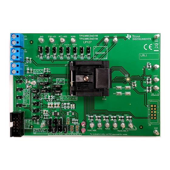
Pins NIRQ, NRST, and WDO are open drain outputs and require an external pull up resistance to supply voltage. SNVU883 – DECEMBER 2023 TPS389C0xEVM Multichannel Voltage Supervisor with Watchdog and I Submit Document Feedback Evaluation Module Copyright © 2023 Texas Instruments Incorporated... - Page 4 Hardware www.ti.com 2 Hardware 2.1 Additional Images Figure 2-1. TPS389C0XEVM Board Front Figure 2-2. TPS389C0XEVM Board Back TPS389C0xEVM Multichannel Voltage Supervisor with Watchdog and I SNVU883 – DECEMBER 2023 Evaluation Module Submit Document Feedback Copyright © 2023 Texas Instruments Incorporated...
- Page 5 - MON6). A description of the connections needed when using TPS389C0300CRTERQ1 is provided in Section 2.4 8. If applicable, then connect any available remote sense to GND. 9. The description of the TPS389C0XEVM connections can be found in Figure 2-3.
-
Page 6: Evm Connectors
EVM. GND for EVM GND for EVM. Test point functionality is dependent on TPS389C0x-Q1 variant used. TPS389C0xEVM Multichannel Voltage Supervisor with Watchdog and I SNVU883 – DECEMBER 2023 Evaluation Module Submit Document Feedback Copyright © 2023 Texas Instruments Incorporated... - Page 7 Hardware 2.3.2 EVM Jumpers Table 2-2 lists the jumpers on the TPS389C0XEVM. As ordered, the EVM has thirty-five (32) jumpers installed. Table 2-2. List of On-board Jumpers JUMPER JUMPER CONFIGUATION DESCRIPTION VAUX For connecting VAUX power to the EVM...
- Page 8 C bus repeaters, comparators, two LDOs, socket and solder down footprints, and the ability to monitor up to six voltage rails. The TPS389C0XEVM also provides the ability for each monitored rail to be voltage divided down by resistor dividers on each of the monitored and input lines.
-
Page 9: Jumper Settings
1. Connect 5 V to turret MON2 and 3.3 V to turret MON3 of TPS389C0XEVM. 2. Connect the TPS389C0XEVM VDD and VAUX inputs to a 3.3 V external power supply. Note that the voltage and current limits of the power supply must be set at 3.3 V and 10 mA. - Page 10 16. Steps 14 and 15 require that polling is halted to complete the desired I2C write operation. 17. Steps 10 through 15 refer to Figure 2-5 below. Figure 2-5. TPS389C0XEVM GUI Setup for Monitoring Two Voltage Supply Rails TPS389C0xEVM Multichannel Voltage Supervisor with Watchdog and I SNVU883 – DECEMBER 2023 Evaluation Module Submit Document Feedback Copyright ©...
- Page 11 Software 3 Software 3.1 Setup and GUI Installations 3.1.1 TPS389C0XEVM Software Setup Follow the steps below for TPS389C0XEVM GUI software installation: 1. Download the Fusion Digital Power Designer Platform GUI for TPS389C0XEVM. 2. Open the downloaded file. 3. In the Welcome Wizard window, click Next.
- Page 12 Figure 3-3. Setup Window - Start Menu Selection 7. There is no need to install additional options for this EVM. Click Next. Figure 3-4. Setup Window - Additional Tasks TPS389C0xEVM Multichannel Voltage Supervisor with Watchdog and I SNVU883 – DECEMBER 2023 Evaluation Module Submit Document Feedback Copyright ©...
- Page 13 9. Click on Finish to complete the installation setup and launch the software. Figure 3-6. Installation Complete Window SNVU883 – DECEMBER 2023 TPS389C0xEVM Multichannel Voltage Supervisor with Watchdog and I Submit Document Feedback Evaluation Module Copyright © 2023 Texas Instruments Incorporated...
- Page 14 Section 3.1 have been completed. Feel free to skip the GUI installation if the Fusion Digital Power Designer for TPS389C0XEVM GUI has been installed already. 2. Power the EVM by turning on the power supply. Note that the voltage and current limits at the power supply is set at 3.3 V and 10 mA.
- Page 15 5. Click on Change Scan Mode to select TPS389xxx and then click OK. Figure 3-8. Fusion Scan Window Figure 3-9. Fusion Scan Selection Window SNVU883 – DECEMBER 2023 TPS389C0xEVM Multichannel Voltage Supervisor with Watchdog and I Submit Document Feedback Evaluation Module Copyright © 2023 Texas Instruments Incorporated...
- Page 16 Software www.ti.com 6. Scan for the TPS389C0XEVM by clicking on Scan for TPS389xxx on top left of the window. Figure 3-10. Fusion Scan Window - Scanning for TPS389C0XEVM 7. Once the EVM is discovered, select Click to Configure. Figure 3-11. Fusion Scan Window - Scan for TPS389C0XEVM Completed TPS389C0xEVM Multichannel Voltage Supervisor with Watchdog and I SNVU883 –...
- Page 17 Reset, Telmetry, and Polling (Plotting the monitored voltage rails) sub-windows. Figure 3-12. Fusion Digital Power Device GUI - TPS389C0XEVM (Image #1) 9. The GUI image below continues to show the additional sub-windows that are in the GUI for the TPS389C03- Q1.
- Page 18 10. The last GUI image below shows the last five registers in the Status Registers sub-window. Figure 3-14. Fusion Digital Power Device GUI - TPS389C0XEVM (Image #3) TPS389C0xEVM Multichannel Voltage Supervisor with Watchdog and I SNVU883 – DECEMBER 2023...
- Page 19 Hardware Design Files 4 Hardware Design Files 4.1 TPS389C0XEVM Schematic Figure 4-1. TPS389C0XEVM Main Schematic SNVU883 – DECEMBER 2023 TPS389C0xEVM Multichannel Voltage Supervisor with Watchdog and I2C Evaluation Module Submit Document Feedback Copyright © 2023 Texas Instruments Incorporated...
- Page 20 Hardware Design Files www.ti.com Figure 4-2. TPS389C0XEVM I C Schematic with Buffers TPS389C0xEVM Multichannel Voltage Supervisor with Watchdog and I2C Evaluation Module SNVU883 – DECEMBER 2023 Submit Document Feedback Copyright © 2023 Texas Instruments Incorporated...
- Page 21 4.2.1 Layout Figure 4-4. Component Placement—Bottom Figure 4-3. Component Placement—Top Assembly Assembly Figure 4-6. Layout—Bottom Figure 4-5. Layout—Top SNVU883 – DECEMBER 2023 TPS389C0xEVM Multichannel Voltage Supervisor with Watchdog and I Submit Document Feedback Evaluation Module Copyright © 2023 Texas Instruments Incorporated...
- Page 22 Figure 4-8. Bottom Layer Figure 4-7. Top Layer Figure 4-9. Top Solder Mask Figure 4-10. Bottom Solder Mask TPS389C0xEVM Multichannel Voltage Supervisor with Watchdog and I SNVU883 – DECEMBER 2023 Evaluation Module Submit Document Feedback Copyright © 2023 Texas Instruments Incorporated...
- Page 23 0603 RC0603FR-0710KL Yageo 26.7kΩ RES, 26.7 k, 1%, 0.125 W, AEC-Q200 Grade 0, 0805 ERJ-6ENF2672V Panasonic 0805 SNVU883 – DECEMBER 2023 TPS389C0xEVM Multichannel Voltage Supervisor with Watchdog and I2C Evaluation Module Submit Document Feedback Copyright © 2023 Texas Instruments Incorporated...
- Page 24 1 A Low-Quiescent-Current Low-Dropout (LDO) DRV0006A TLV75718PDRVR Regulator, DRV0006A (WSON-6) Dual-Channel, Low-Power Comparator with SON6 TLV4082DRYR Integrated Reference TPS389C0xEVM Multichannel Voltage Supervisor with Watchdog and I2C Evaluation Module SNVU883 – DECEMBER 2023 Submit Document Feedback Copyright © 2023 Texas Instruments Incorporated...
- Page 25 PACKAGE DESIGNATOR VALUE DESCRIPTION PART NUMBER MANUFACTURE REFERENCE Automotive, Level-Shifting I2C Bus Repeater, DGK0008A TCA9517DGKRQ1 DGK0008A (VSSOP-8) SNVU883 – DECEMBER 2023 TPS389C0xEVM Multichannel Voltage Supervisor with Watchdog and I2C Evaluation Module Submit Document Feedback Copyright © 2023 Texas Instruments Incorporated...
- Page 26 6 Related Documentation Data sheet: TPS389C03-Q1 Multichannel Overvoltage and Undervoltage I2C Programmable Voltage Supervisor and Monitor with Q&A Watchdog TPS389C0xEVM Multichannel Voltage Supervisor with Watchdog and I SNVU883 – DECEMBER 2023 Evaluation Module Submit Document Feedback Copyright © 2023 Texas Instruments Incorporated...
- Page 27 TI products. TI’s provision of these resources does not expand or otherwise alter TI’s applicable warranties or warranty disclaimers for TI products. TI objects to and rejects any additional or different terms you may have proposed. IMPORTANT NOTICE Mailing Address: Texas Instruments, Post Office Box 655303, Dallas, Texas 75265 Copyright © 2023, Texas Instruments Incorporated...
Need help?
Do you have a question about the TPS389C0xEVM and is the answer not in the manual?
Questions and answers